


7 60-2242—2
T921A,B,E-G
SETTING AND ADJUSTING • OPERATION
This switch energizes a heater that offsets the ther-
mostat approximately 10° F [6° C], lowering the
temperature for night operation. Leave this switch in
the OFF position for normal operation; turn it to the
ON position for lower night time temperature.
CALIBRATION
IMPORTANT: Do not recalibrate unless the thermostat
continues to be out-of-adjustment after several hours
of operation.
T921 Thermostats are calibrated at the factory so when
the room temperature matches the setpoint temperature, the
wiper is at the center of the active potentiometer winding.
If the thermostat is out of calibration, proceed as follows
(see Fig. 11):
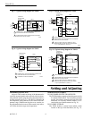
1. Remove the thermostat cover.
2. Turn the thermostat setting adjustment knob or an
Allen wrench until the valve or damper motor is at mid-
point.
3. Loosen the indicator lock screw and move the indica-
tor to room temperature. Tighten the lock screw.
4. Replace the thermostat cover. Recheck the calibra-
tion and repeat the procedure if necessary.
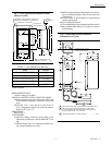
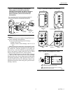
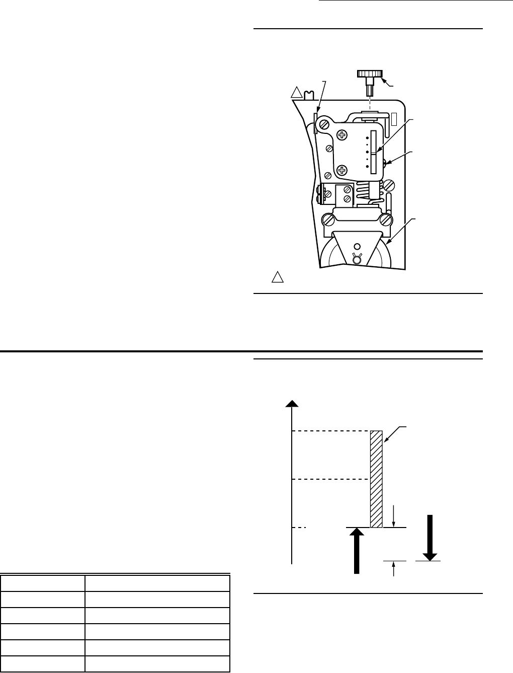
Fig. 11—Internal view of vertically mounted
T921 (horizontally mounted model is similar).
TEMPERATURE
SETTING
INDICATOR
INDICATOR
LOCK SCREW
BELLOWS
SETTING
ADJUSTMENT KNOB
POTENTIOMETER
WIPER
1
1
SUMMER-WINTER (COOL-HEAT) CHANGEOVER SWITCH ON
T921B ONLY; NIGHT SETBACK SWITCH ON T921E ONLY.
M9039
80
70
60
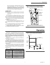
In the T921, a vapor-filled bellows moves the potenti-
ometer wiper by expanding or contracting in proportion to
temperature changes. As the wiper moves, the appropriate
motor winding is energized, opening or closing the valve or
damper to compensate for the temperature change in the
controlled area.
Operation of the auxiliary switch in the T921F,G is
shown in Figs. 12 and 13.
See Table 3 for the throttling range of each thermostat.
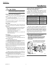
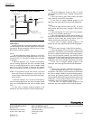
The T921F Auxiliary Switch makes R-W at the low end of
the throttling range on temperature rise and makes R-B at
2° F [1° C] below the low end of the throttling range on
temperature fall.
The T921G Auxiliary Switch makes R-W at the high
end of the throttling range on temperature fall and R-B at
1° F [0.5° C] above the high end of the throttling range on
temperature rise.
TABLE 3—THERMOSTAT THROTTLING RANGES
Fig. 12—T921F auxiliary switch operation.
Model Throttling Range
T921A 2.5° F [1.5° C] midscale
T921B 2.5° F [1.5° C] midscale
T921E 4° F [2° C]
T921F 6° F [4° C]
T921G 5° F [3° C]
M5990
+3˚ F
[+1.5˚ C]
SETPOINT
TEMPER-
ATURE
-3˚ F
[-1.5˚ C]
R-W MAKES
TEMPERATURE
RISE
2˚ F [1˚ C]
DIFFERENTIAL
R-B MAKES
TEMPERATURE
FALL
THROTTING
RANGE (6˚ F [4˚ C])
TEMPERATURE
Operation