


5 60-2242—2
T921A,B,E-G
INSTALLATION
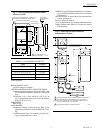
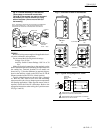
Fig. 4—Vertical mounting of T921A,B,E-G
Thermostats on horizontal conduit box.
T921A,B,E Thermostats can also be mounted
horizontally on vertical conduit box using
add-on faceplate. (Do not mount T921F,G
horizontally.)
HONEYWELL
80
70
60
60 70 80 90
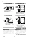
NOTE: ACCESSORY FACEPLATE FOR USE WHEN THE THERMOSTAT
IS MOUNTED HORIZONTALLY. PEEL OFF BACKING AND APPLY
OVER VERTICAL FACEPLATE AFTER MOUNTING IS COMPLETE.
MOUNTING
SCREWS
BACKPLATE
127246A
ACCESSORY
ADAPTER
PLATE
CONDUIT
BOX
COVER
LOCKING
SCREW
M9036
WIRING
Be sure all wiring must complies with applicable electri-
cal codes, ordinances and regulations.
Do not exceed the following electrical ratings:
Voltage: 24 to 30 Vac.
Auxiliary Switch Contact Ratings: 100 VA at 30
Vac.
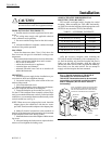
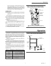
Make all electrical connections to the terminals on the
back of the thermostat before mounting the instrument onto
the conduit box. Terminal locations for all models are
shown in Fig. 5. Note the difference in terminal designa-
tions for the auxiliary switch on the T921F and G. The H
(Heater) terminal on the T921E is a black leadwire.
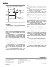
Typical wiring diagrams are shown in Figs. 6 through
10. Wire the T921 color-to-color when the modulating
motor must drive the valve or damper open on temperature
fall (heating application). When opposite motor action is
required, reverse the B and W connections. Refer to the
appropriate instructions when wiring the 2-position actua-
tor (Figs. 9 and 10).
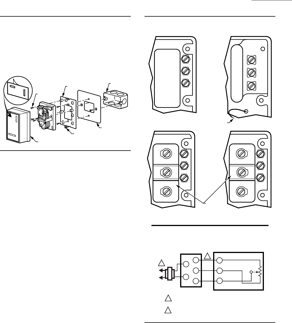
Fig. 5—Terminals on back of thermostats.
T921A, B
T921GT921F
B
W
R
TOP
RBW
RBW
B
W
R
T921E
TOPTOP
AUXILIARY
SWITCH
TERMINALS
B
W
R
TOP
B
W
R
H (HEATER)
M9038
(BLACK)
Fig. 6—Typical wiring diagram for T921A.
L1
(HOT)
L2
1
1
SERIES 90
MODULATING
MOTOR
T921A
M5989
POWER SUPPLY. PROVIDE DISCONNECT MEANS AND
OVERLOAD PROTECTION AS REQUIRED.
INTERCHANGE B AND W CONNECTIONS TO REVERSE
DIRECTION OF MOTOR TRAVEL.
T
R
W
B
T
B
W
R
2
2
TRANSFORMER
B
W