T8775A,C THE DIGITAL ROUND
™
NON-PROGRAMMABLE THERMOSTATS
5 68-0279
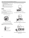
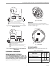
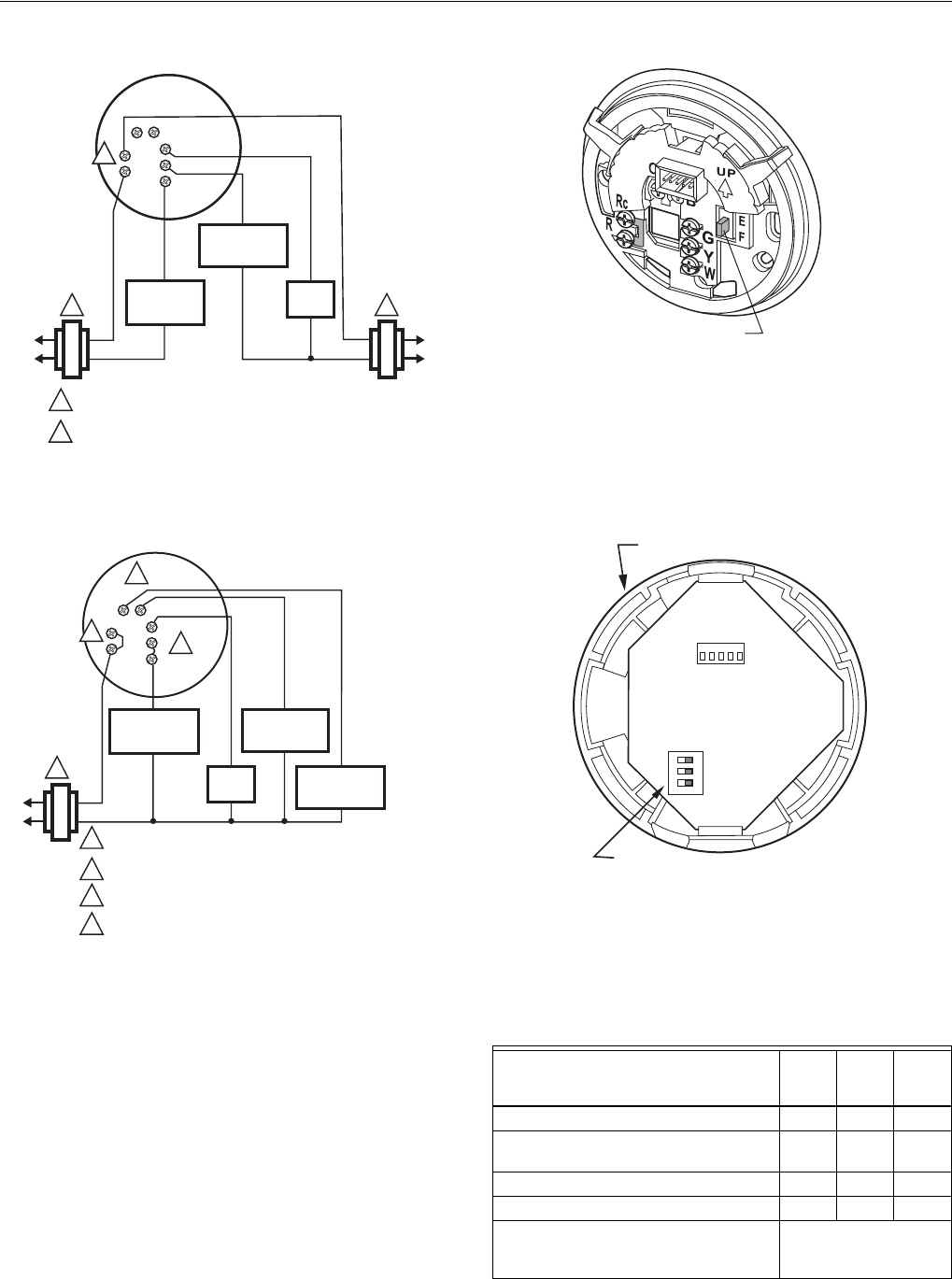
Fig. 10. Typical hookup of T8775C in heat-cool system
with two transformers.
Fig. 11. Typical hookup of T8775C in single-stage heat
pump system.
CUSTOMIZE THERMOSTAT
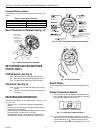
Setting Fuel Switch (T8775C only)
The fuel switch is preset at the factory in the F position. See
Fig. 12. This is the correct setting for gas or oil systems. If the
T8775C is being installed on an electric heat system, or a heat
pump, set the switch to the E position. The E position allows
the fan to turn on immediately with the heating equipment in a
system where the G terminal is connected.
Fig. 12. Fuel switch.
DIP Switch
To adjust the heat cycle rate or the Fahrenheit/Celsius
temperature display, locate DIP switch 1, 2 and 3 on the back
of the thermostat. See Fig. 13.
Fig. 13. DIP switch.
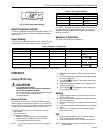
Set Heat Cycle Rate
Use DIP switches 1 and 2 to set the heat cycle rate. See
Table 1.
Table 1. Heat Cycle Rate.
1
2
1
HEATING
RELAY OR
VALVE COIL
COMPRESSOR
CONTACTOR
FAN
RELAY
M1951
7
1 POWER SUPPLY. PROVIDE DISCONNECT MEANS
AND OVERLOAD PROTECTION AS REQUIRED.
REMOVE FACTORY INSTALLED JUMPER BETWEEN R AND R
C
.
2
W
R
Rc
B
Y
G
1
4
COMPRESSOR
CONTACTOR
HEAT
CHANGEOVER
VALVE
COOL
CHANGEOVER
VALVE
FAN
RELAY
M1951
6
1 POWER SUPPLY. PROVIDE DISCONNECT MEANS
AND OVERLOAD PROTECTION AS REQUIRED.
2 FACTORY INSTALLED JUMPER.
3 USE A JUMPER WIRE (NOT SUPPLIED) TO CONNECT W TO
Y.
4 USE EITHER O OR B FOR HEAT PUMP CHANGEOVER.
3
2
W
R
Rc
B
O
Y
G
Heating System
Cycles
Per
Hour
DIP
Switch
1
DIP
Switch
2
Steam, Gravity 1 On On
High Efficiency Warm Air (90%+
efficiency), Hot Water, Heat Pump
3OffOn
Gas or Oil Warm Air (factory setting) 6 Off Off
Electric Warm Air 9 On Off
In Floor Radiant Heat Check with manufacturer
for recommended cycle
rate.
M1949
7
FUEL SWITCH
ON
1 2 3
M19567
BACK OF THERMOSTAT
DIP SWITCH


