


569-0348—1
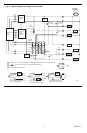
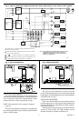
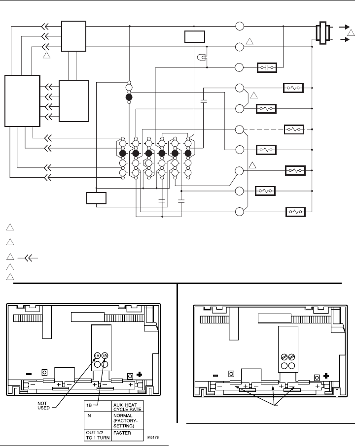
Fig. 6—T8611R 2-stage heat/1-stage cool thermostat. Exact replacement for York model no. 2ET11700224.
MONITOR
AUXILIARY
HEAT RELAY
HEAT 2
L1
(HOT)
L2
HEAT
OFF
AUTO
SYSTEM
SWITCH
AUTO
ON
FAN
SWITCH
1
STAGE 1
HEAT RELAY
EMERGENCY
HEAT RELAY
FAN RELAY
CHANGEOVER
RELAY (HEAT)
COMPRESSOR
CONTACTOR
EM. HT.
COOL
CHANGEOVER
RELAY (COOL)
EM. HEAT
LED (RED)
HEAT 1
THERMOSTAT
LOGIC
CIRCUIT
SUBBASE
LOGIC/
CONTROL
CIRCUIT
R
B
X
W2
E
W1
G
O
H
Y1
TRANSFORMER
POWER
SUPPLY
HIGH
LIMIT
HIGH
LIMIT
2
3
POWER SUPPLY. PROVIDE DISCONNECT MEANS AND OVERLOAD
PROTECTION AS REQUIRED.
REMOVE JUMPER FOR SYSTEM WITH ISOLATED STAGE 1 HEATING
AND COOLING CONNECTIONS.
DENOTES THERMOSTAT TO SUBBASE INTERCONNECT.
REMOVE JUMPER FOR SYSTEM WITH ISOLATED EMERGENCY HEAT.
TRANSFORMER COMMON IS CONNECTED TO B TERMINAL.
1
2
3
4
5
4
5
M3206
NOTE: THIS DIAGRAM IS FOR USE WHEN REPLACING ONLY YORK
THERMOSTAT MODEL NO. 2ET11700224. USING THIS
DRAWING FOR OTHER INSTALLATIONS CAN RESULT IN
DAMAGE TO THERMOSTAT.
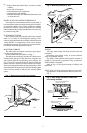
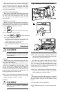
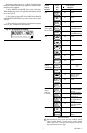
Fig. 8—Battery placement.Fig. 7—Cycle rate adjustment.
CYCLE RATE ADJUSTMENT
To custom-tailor the thermostat’s cycling performance to
different types of heating equipment, a cycle rate adjustment
screw is provided on the back of the thermostat. Correct
setting of this screw will provide optimum savings.
NOTE: Most applications will not require a change in
cycle rate.
The room air temperature will normally vary slightly from
the comfort temperature setting with the cycling of the heat
pump or auxiliary heater.
The cycle rate of this thermostat is factory-set for heat
pumps. The heat pump compressor cycle rate can be adjusted
by turning the cycle rate adjustment screw located on the back
of the thermostat, see Fig. 7.
INSTALLING BATTERIES
Three AAA alkaline batteries are provided as backup to
prevent program loss in event of power outage. Batteries are
included with thermostat. Install batteries in back of thermo-
stat as shown in Fig. 8.
Without battery backup, the program will remain about 20
seconds in event of power loss. When batteries are first
installed, the display will flash 1:00 PM and 32°.
BATTERY PLACEMENT
(NOTE CORRECT PLUS
AND MINUS DIRECTION)
M372A