


T8400C, T8401C AND T8424C,D ELECTRONIC THERMOSTATS
5 68-0180-3
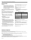
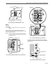
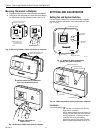
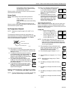
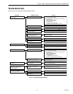
Fig. 5. Mounting the T8424 wallplate to wall.
Wiring
IMPORTANT
Use an 18-gauge maximum wire for wiring the ther-
mostats.
All wiring must comply with local electrical codes and
ordinances. Disconnect the power supply to prevent electrical
shock or equipment damage.
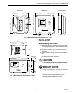
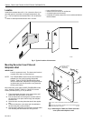
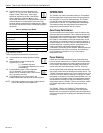
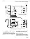
NOTE: To ensure proper mounting of thermostat, restrict all
wiring to the shaded area on the left side of the termi-
nals. See Fig. 6 or 7.
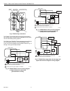
Fig. 6. Restrict T8400 and T8401 wiring to shaded area.
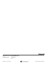
Fig. 7. Restrict T8424 wiring to shaded area.
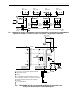
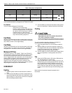
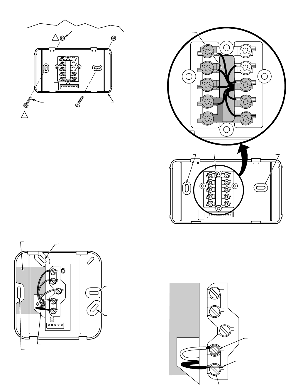
The shape of the terminals permits insertion of straight or
wraparound wiring connections; either method is acceptable.
See Fig. 8 or 9.
Fig. 8. T8400 and T8401 wiring connections.
M12202A
WALL
WALL
ANCHORS (2)
WALLPLATE
WHEN USING WALL ANCHORS, DRILL 3/16 INCH
HOLES FOR DRYWALL, 7/32 INCH HOLES FOR
PLASTER OR WOOD.
MOUNTING
SCREWS (2)
1
1
M11023
ALTERNATE
MOUNTING
SCREW HOLE
MOUNTING
SCREW
HOLE
MOUNTING
SCREW HOLE
ALTERNATE MOUNTING
SCREW HOLE
KEEP WIRING IN
SHADED AREA
WIRING ENTRANCE HOLE
W
Y
G
R
C
KEEP WIRING IN
SHADED AREA
MOUNTING
SCREW HOLE
MOUNTING
SCREW HOLE
WIRING ENTRANCE
HOLE
M20211
G
C
R
Y
W1
Y2
W2
B
O
M11232
FOR WRAPAROUND
STRIP 7/16 IN. (11 MM)
FOR STRAIGHT INSERTION
STRIP 5/16 IN. (8 MM)
TERMINAL SCREW
W
G
Y
R
C