


HEAT PUMP THERMOSTAT
69-1043-2 2
Location
Locate the thermostat between 4 ft (1.2m) and 5 ft (1.5m)
above the floor in an area with good air circulation at
average room temperature.
NOTE: Because of height restrictions of some disabled
users, it may be necessary to lower the thermo-
stat location to 4 ft (1.2m) above the floor.
Do not install thermostat where it can be affected by:
— drafts, or dead spots behind doors and in corners.
— hot or cold air from ducts.
— radiant heat from sun, appliances or fireplaces.
— concealed pipes and chimneys.
— unheated (uncooled) areas such as an outside wall
behind the thermostat.
This thermostat is a precision instrument and was
carefully adjusted at the factory. Handle it carefully.
Mounting
The T841A,B can be mounted directly on a wall or a
horizontal outlet box. Choose the method that best fits
your installation. In replacement applications, check the
existing thermostat wires for cracked or frayed insulation.
Replace any wires in poor condition.
To remove the thermostat cover:
1. Grasp thermostat cover at the top and bottom with
one hand.
2. Pull outward on the bottom edge of the cover until
it snaps free of the thermostat base.
3. Carefully remove and save the packing material
surrounding the mercury switches.
Wiring
All wiring must comply with local codes and ordinances.
Follow equipment manufacturer wiring instructions when
available.
NOTE: Four screws are provided with the thermostat;
only two are required for mounting.
1. Run wiring (if necessary) to the location. If wiring is
plastered into the wall, make a hole next to the wire
and loosen the wires so they can be pushed back
into the wall later.
2. Thread the wires through the hole.
3. Pull the wires through the entrance hole on the
wallplate.
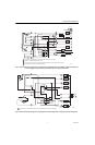
4. Connect the wires to the terminals on the back of
the thermostat. See Fig. 1-3.
5. Push the excess wire back through the hole and
plug any openings with packing material to prevent
drafts that can affect thermostat performance.
6. Use two of the four screws provided to loosely
secure the thermostat and the wallplate to the wall
or outlet box through the two middle mounting
holes. See Fig. 1.
NOTE: The sheet metal screws included with the ther-
mostat are designed for use in plaster walls that
do not need anchors.
IMPORTANT
An incorrectly leveled thermostat causes inac-
curate temperature control.
7. Exactly level the thermostat using a spirit level or
plumb line.
8. Tighten the screws in the middle mounting holes.
9. Replace the thermostat cover.
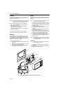
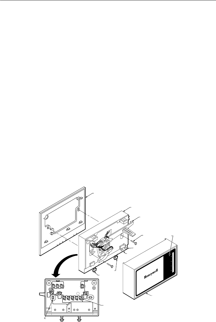
Fig. 1. Mounting thermostat to wallplate (T841A model shown).
80
70
60
50
WALLPLATE
T841 BASE
MOUNTING
SCREWS (2)
T841 COVER
M11427
TEMPERATURE
SETPOINT LEVER
EH H O C
A O
SETPOINT
SCALE
EM. HEAT
LED
AUX. HEAT
LED
FAN SWITCH
SYSTEM SWITCH
MOUNTING
HOLES (4)
WIRING TERMINAL
(UP TO 12)
BACK OF DEVICE
HEAT PUMP THERMOSTAT
EM. HEAT HEAT OFF COOL
AUTO ON
FAN