


T8400C AND T8401C ELECTRONIC THERMOSTATS
3 69-1480-1
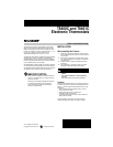
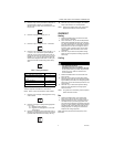
Fig. 3. Restrict wiring to shaded area.
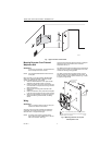
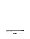
Fig. 4. Wiring connections.
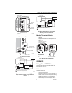
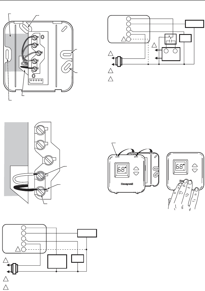
Fig. 5. T8400C/T8401C heat-cool wiring diagram in
single transformer system with gas heat/electric
cooling.
Fig. 6. T8400C/T8401C heat-cool wiring
diagram in oil heating/electric cooling system.
Oil primary has its own transformer.
Mounting Thermostat to Wallplate
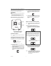
1. Engage the tabs at the top of the thermostat and
wallplate.
2. Swing down the thermostat and press the lower
edge of the thermostat onto the wallplate to latch.
See Fig. 7.
Fig. 7. Mounting thermostat wallplate.
OPERATION
Setting FAN and SYSTEM Switches
Fan and system settings are controlled manually by
using the switches located at the bottom of the
thermostat case. See Fig. 8.
FAN Switch
Fan switch settings are:
On: The fan runs continuously. Use for improved air
circulation and air quality.
Auto: Normal setting for most homes. In cooling, the
fan starts and stops with the cooling equipment. In
heating, the fan is controlled directly by the heating
equipment and may start a few minutes after the
heating equipment turns on (on most systems).
When using an electric heat thermostat, the fan
starts and stops with the heating equipment.
M11023
ALTERNATE
MOUNTING
SCREW HOLE
MOUNTING
SCREW
HOLE
MOUNTING
SCREW HOLE
ALTERNATE MOUNTING
SCREW HOLE
KEEP WIRING IN
SHADED AREA
WIRING ENTRANCE HOLE
W
Y
G
R
C
M11232
FOR WRAPAROUND
STRIP 7/16 IN. (11 MM)
FOR STRAIGHT INSERTION
STRIP 5/16 IN. (8 MM)
TERMINAL SCREW
W
G
Y
R
C
L1
(HOT)
L2
1
2
1
2
W
Y
G
R
C
COOLING
CONTACTOR
FAN
RELAY
HEATING
PRIMARY
CONTROL
24V
POWER SUPPLY. PROVIDE DISCONNECT MEANS AND
OVERLOAD PROTECTION AS REQUIRED.
IN T8401C INSTALLATIONS, CONNECT C TERMINAL.
M11021B
T8400C, T8401C
L1
(HOT)
L1
(HOT)
L2
L2
1
1
2
1
W
Y
G
R
C
2
COOLING
CONTACTOR
FAN
RELAY
OIL PRIMARY
CONTROL
T
T
24V
POWER SUPPLY. PROVIDE DISCONNECT MEANS AND
OVERLOAD PROTECTION AS REQUIRED.
IN T8401C INSTALLATIONS, CONNECT C TERMINAL.
M11022B
T8400C, T8401C
M18416
FAN SYSTEM
Auto On
Cool Off Heat
DASHED LINES INDICATE TABS
ON BACK OF THERMOSTAT
FAN SYSTEM
Auto
Cool Off Heat
ENGAGE TABS AT TOP
OF THERMOSTAT WITH
SLOTS ON WALLPLATE.
A
B
PRESS LOWER EDGE OF
CASE TO LATCH.
Set
Room
Set
Room