


English: Page 1 • Français: Page 6 • Español: Página 11
3
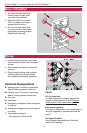
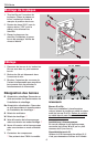
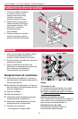
Base installation
1 Pull wires through wire hole.
Position base on wall, level
and mark hole positions.
2 Drill holes (3/16” for drywall,
7/32” for plaster), then tap in
supplied wall anchors.
3 Pull wire through base, posi-
tion over anchors, then insert
and tighten mounting screws.
Check level if desired.
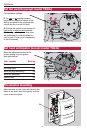
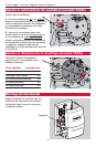
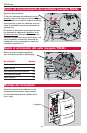
Wiring
1 Loosen screw terminals, insert bare
wires beneath screws, then re-tighten
screws.
2 Push excess wire back into the wall
opening.
3 Plug the wall opening with nonflam-
mable insulation to prevent drafts
from affecting thermostat operation.
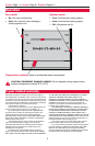
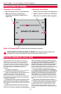
Terminal Designations
R Heating power. Connect to secondary
side of heating system transformer.
RcCooling power. Connect to secondary
side of cooling system transformer. **
G Fan relay.
W Heat relay. **
B Heat pump changeover valve energized
in heating. **
O Heat pump changeover valve energized
in cooling.
Y Compressor contactor.
** Not present in T834L model
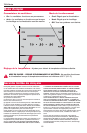
NOTES
R & Rc terminals
In single-transformer system, leave metal
jumper in place between R & Rc. Remove
metal jumper if two-transformer system.
Heat pump systems
If wiring to a heat pump, use a small piece of
wire (not supplied) to connect terminals W
and Y.
Wire specifications
Use 18-gauge thermostat wire. Shielded
cable is not required.