


2
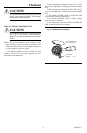
Fig. 2—T822C in typical cooling application.
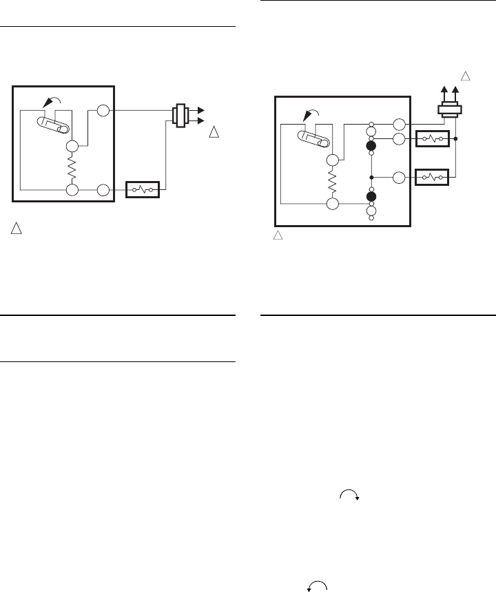
Fig. 3—T822E in typical cooling application.
POWER SUPPLY. PROVIDE DISCONNECT MEANS AND OVERLOAD
PROTECTION AS REQUIRED.
M2305
T822C
1
L1
(HOT)
L2
TEMP. RISE
C1
C1
ANTICIPATOR
R
Y
COMPRESSOR
RELAY
1
POWER SUPPLY. PROVIDE DISCONNECT MEANS AND OVERLOAD
PROTECTION AS REQUIRED.
M1293
T822E
L1
(HOT)
L2
TEMP. RISE
C1
C1
ANTICIPATOR
R
G
Y
FAN RELAY
COMPRESSOR
CONTACTOR
1
FAN
SWITCH
ON
AUTO
SYSTEM
SWITCH
OFF
AUTO
1
Settings and Adjustment
TEMPERATURE SETTING
Move the temperature setting lever to the desired
control point on the temperature scale. On positive OFF
models, the control circuit is broken when the lever is
moved to the extreme high end of the temperature scale.
T822E FAN AND SYSTEM SWITCHING
The fan switch controls fan operation as follows:
AUTO— fan operates in response to the thermostat
call for cooling.
ON— fan operated continuously.
The system switch controls system operations as
follows:
OFF—cooling control system is disabled.
AUTO—cooling control system operates in response
to the thermostat call for cooling.
RECALIBRATION
These thermostats are calibrated at the factory and
should not need recalibration. If the thermostat seems
out of adjustment, first check for accurate leveling. To
check calibration, proceed as follows:
1. Move the temperature setting lever to the low end
of the temperature scale.
2. Remove the thermostat cover. Move the setting
lever until the switch just makes contact. The mercury in
the switch will drop to the contact end of the tube.
3. Replace cover and wait five minutes for the cover
and the thermostat to lose the heat it has gained from
your hands. If the thermostat pointer and the setting
lever indicator read approximately the same, no
recalibration is needed.
If recalibration appears necessary, proceed as fol-
lows:
1. Place the temperature setting lever at the same
setting as the thermometer. Remove cover.
2. Insert 104994A Calibration Wrench (order sepa-
rately) onto the hex nut under the coil. See Fig. 4.
Holding the setting lever so it does not move, turn the
wrench clockwise until the switch just breaks con-
tact. Remove wrench and replace cover.
3. Move the setting lever to a low setting. Wait at
least five minutes for temperature to stabilize.
4. Slowly move the setting lever until it reads the
same as the thermometer.
5. Remove cover. Holding the setting lever so it does
not move, reinsert wrench and carefully turn counter-
clockwise until the mercury just rolls to the left
end of the tube but no farther.
6. Recheck calibration. Set thermostat system switch
for desired operation and replace cover.