


3 68-0148—1
T8131A,B,C; T8132A,B,C
SPECIFICATIONS • INSTALLATION
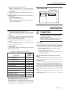
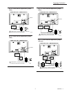
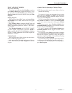
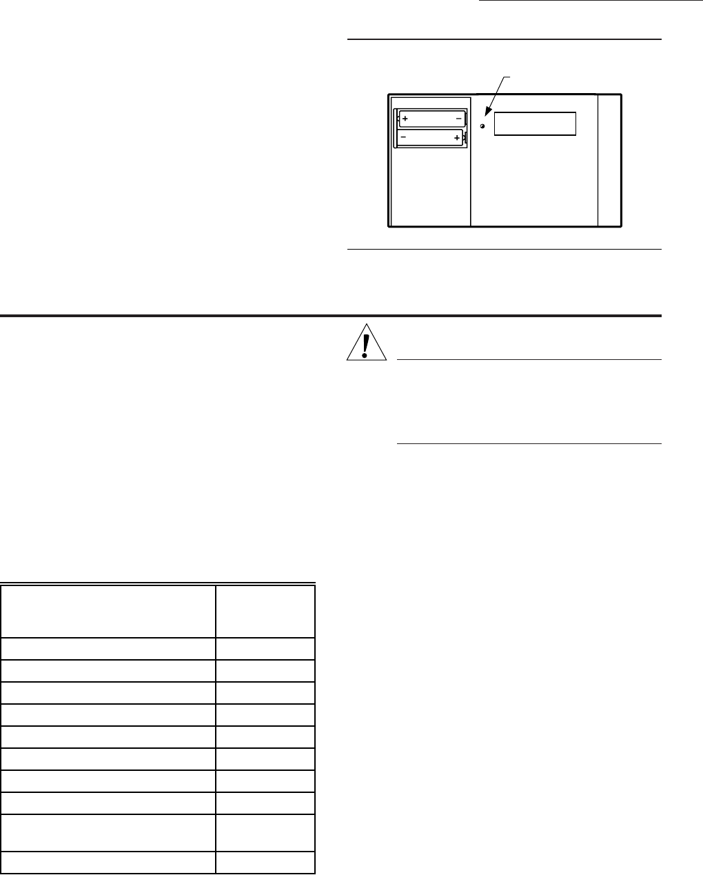
Fig. 2—T8131 LED.
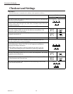
CYCLES PER HOUR ADJUSTMENT:
Heating: Field adjustable to 3, 6, or 9 cph ±10 percent.
Cooling: Factory-set at 3 cph ±10 percent (not field
adjustable).
CALIBRATION: Thermostat and thermometer self-cali-
brating to ±1.25° F.
FINISH: All models available in taupe and Premier White™.
ACCESSORIES:
205013 Isolation Relay kit.
205014 Transformer Plug-in Kit.
205015 International Organization for Standardization
Relay and Transformer.
Installation
WHEN INSTALLING THIS PRODUCT…
1. Read these instructions carefully. Failure to follow
instructions can damage product or cause a hazardous
condition.
2. Check the ratings given in the instructions and on the
product and the compatibility chart below to make sure the
product is suitable for your application.
3. Make sure installer is a trained, experienced service
technician.
4. After completing installation, use these instructions
to check out product operation.
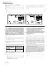
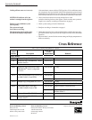
COMPATIBILITY
Check Table 1 to make sure the thermostat is compatible
with the intended system.
TABLE 1—COMPATIBILITY CHART.
System Type
Compatible
with
T8131/T8132
Gas—Standing Pilot Yes
Gas—Electronic Ignition Yes
Gas-Fired Boilers Yes
a
Gas—Millivolt No
Oil-Fired Boilers Yes
a
Oil-Fired Furnace Yes
Electric Furnace Yes
Electric Air Conditioning Yes
Baseboard Electric
(120/240 Line Volt)
No
Heat pumps/Multistage Equipment No
Not compatible with any 120/240 volt circuit.
Not designed for steam or gravity systems.
a
Compatible with 2-wire Honeywell zone valves. Isolating
relay required for 3-wire thermostats for zone valves. Not
compatible with 2-wire White Rodgers no. 1361 Valves.
WARNING
ELECTROCUTION HAZARD CAN
CAUSE PROPERTY DAMAGE, SEVERE
INJURY, OR DEATH.
Disconnect power supply before wiring to pre-
vent electrical shock or equipment damage.
LOCATION
Locate the thermostat about 5 ft [1.5m] above the floor
in an area with good air circulation at average temperature.
Do not mount the thermostat where it may be affected by:
—drafts or dead spots behind doors and in corners.
—hot or cold air ducts.
—concealed pipes and chimneys.
—unheated (uncooled) areas such as an outside wall
behind the thermostat.
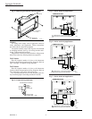
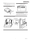
MOUNT THERMOSTAT MOUNTING PLATE
(FIG. 2)
Position mounting plate on wall. Use spirit level to make
sure mounting plate is level. Use a pencil to mark the two
mounting holes.
Level for appearance only; thermostat will function
properly even when not level. Tighten mounting screws.
Remove mounting plate from wall, and drill 3/16 inch
holes in wall (if drywall) as marked. For firmer material
such as plaster or wood, drill 7/32 inch holes. Gently tap
anchors (provided) into drilled holes until flush with the
wall.
Reposition mounting plate over holes, pulling wires
through wiring opening. Loosely insert two mounting
screws into holes.
LED LIGHTS WHEN
PROPERLY CONNECTED
M9365
POWER