


68-0148—1 4
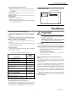
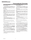
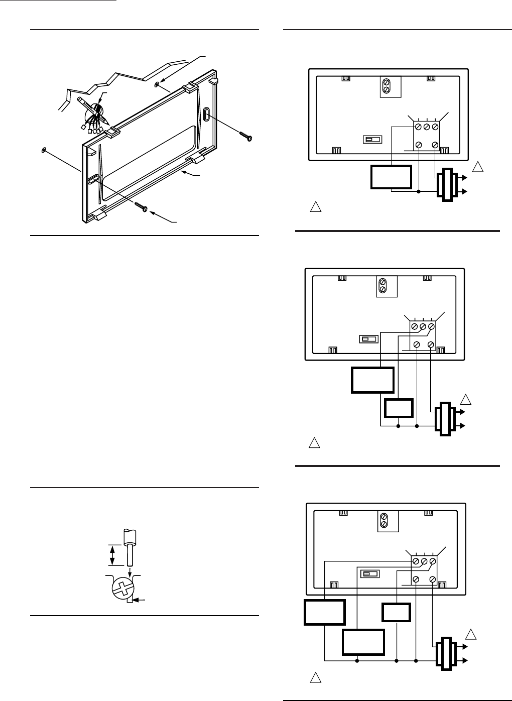
Fig. 3—Mounting thermostat mounting plate.
T8131A,B,C; T8132A,B,C
INSTALLATION
WALL
WIRES THROUGH
WALL OPENING
WALL
ANCHORS (2)
MOUNTING
PLATE
MOUNTING
SCREWS (2)
M1718
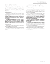
WIRING
All wiring must comply with all applicable electrical
codes, ordinances, and regulations. Follow instructions
provided with the controlled equipment.
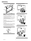
Loosen the terminal screws and slip each wire beneath
its matching terminal. See Fig. 4 for wiring insertion tech-
niques. Tighten terminals securely.
Plug the hole in the wall with insulation to help prevent
drafts from adversely affecting thermostat operation.
T8131 Models
Run the required number of wires to the thermostat
location (check the appropriate wiring diagram). Refer to
Figs. 5 through 7 for typical wiring diagrams.
T8132 Models
Run the required number of wires to the thermostat
location (check the appropriate wiring diagram). Refer to
Figs. 8 through 11 for typical wiring diagrams.
In 5-wire installations only, be sure to remove the fac-
tory-installed jumper connecting terminals R and Rc.
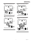
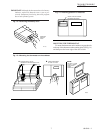
Fig. 4—Proper wiring technique.
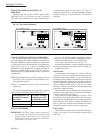
Fig. 5—3-wire heat-only application.
Fig. 7—5-wire heat/cool application.
Fig. 6—4-wire cool-only application.
C
R
W Y G
B
A
3-WIRE HEAT-ONLY
M9213
POWER SUPPLY. PROVIDE DISCONNECT MEANS
AND OVERLOAD PROTECTION AS REQUIRED.
1
1
L1
(HOT)
L2
HEATING
RELAY OR
VALVE COIL
C
R
W Y G
B
A
4-WIRE COOL-ONLY
L1
(HOT)
L2
POWER SUPPLY. PROVIDE DISCONNECT MEANS AND
OVERLOAD PROTECTION AS REQUIRED.
1
1
M9212
COOLING
CONTACTOR
COIL
FAN
RELAY
C
R
W Y G
B
A
5-WIRE HEAT/COOL
L1
(HOT)
L2
POWER SUPPLY. PROVIDE DISCONNECT MEANS AND
OVERLOAD PROTECTION AS REQUIRED.
1
1
HEATING
RELAY OR
VALVE COIL
M9214
COOLING
CONTACTOR
COIL
FAN
RELAY
M3825
INSERT
STRAIGHT
UNDER
SCREW HEAD
5/16 in.
[8 mm]
STRIP
END OF WIRE
VISIBLE HERE
PROPER WIRING TECHNIQUE