


T8112D PROGRAMMABLE THERMOSTAT
68-0206
5
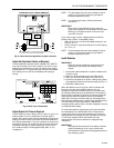
Fig. 8. 5-wire heat/cool application (jumper removed).
Adjust Fan Operation Switch, as Required
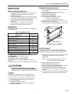
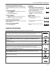
The thermostat fan operation switch, labeled FUEL SWITCH
(see Fig. 9) is factory set in the F position. This is the correct
setting for most systems. If you have an electric heat system,
set the switch to E. In systems with the G terminal connected,
the E setting turns on the fan immediately with heating or
cooling.
R
Rc
W Y G
B D
A C
5-WIRE HEAT/COOL (JUMPER REMOVED)
L1
(HOT)
L2
POWER SUPPLY. PROVIDE DISCONNECT MEANS AND
OVERLOAD PROTECTION AS REQUIRED.
1
M1711B
L1
(HOT)
L2
COOLING
CONTACTOR
COIL
FAN
RELAY
HEATING
RELAY OR
VALVE COIL
1 1
M3669
R
Rc
W Y G
B D
A C
THERMOSTAT BACK
FOR HIGH EFFICIENCY FURNACE (90%+ AFUE)
SCREW A–OUT 1 TURN
SCREW B–IN
FUEL SWITCH – F POSITION
F
E
FUEL SWITCH
WARM AIR
FURNACE
A–IN
ADJUST SCREWS THROUGH HOLES
TO SELECT OPERATION DESIRED
B–IN
FUEL SWITCH
POSITION
HEATING SYSTEM
ELECTRIC
FURNACE
HOT WATER
BOILER
A–IN
A–OUT
1 TURN
B–IN
B–OUT
1 TURN
E
F
F
ADJUST:
NOTE: This thermostat does not have a setting for steam/
gravity air. Cycles would not be long enough for
accurate temperature control.
NOTE: For condensing furnaces, follow manufacturer
instructions.
IMPORTANT
When using a high efficiency furnace such as a
90 percent or greater AFUE (Average Fuel Utilization
Efficiency) unit, adjust screw A out one turn and
screw B In one turn.
If you want a longer on-time, readjust screws A and B as
follows (refer to Table 1 Compatibility Chart):
• Warm Air Furnace—set at the Hot Water setting (A—out
one turn, B—in).
• Electric Furnace—leave at the Warm Air Furnace setting
(A—in, B—in).
NOTE: This thermostat does not have a setting for steam/
gravity air. Cycles would not be long enough for
accurate temperature control.
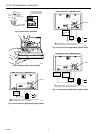
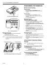
Install Batteries
IMPORTANT
Batteries must be installed for programming and
operating the thermostat and heating/cooling
system.
1. Use two AA alkaline batteries; nonalkaline batteries will
not last as long.
2. Make sure the thermostat is set to the Off position.
3. Use a coin to remove the battery door (see Fig. 10).
4. Install the new batteries as shown, making sure positive
and negative terminals are oriented correctly (see Fig. 11).
5. Replace the battery door.
When the batteries are running low, a
bAt Lo
indicator will
flash for one to two months before batteries run out
completely. Replace the batteries as soon as possible after
the indicator starts flashing. If the batteries are not replaced
when the
bAt Lo
indicator is flashing, the indicator eventually
stops flashing. When the batteries are almost completely
dead,
bAt Lo
will stay on without flashing, indicating that the
thermostat and heating/cooling system have stopped working.
The thermostat will not function after the batteries are
completely dead, and the
bAt Lo
indicator disappears, leaving
a completely blank display.
To remove the batteries, press down on the left ends. When
the new batteries are installed within 20 to 30 seconds of
removing the old ones, the thermostat does not have to be
reprogrammed. If the display is blank, the batteries are dead
or incorrectly installed and the thermostat has to be
reprogrammed. See Owner’s Manual for reprogramming
instructions.
IMPORTANT
Although the thermostat has a low battery indicator,
replace the batteries once a year to prevent the
thermostat from losing time and programming due to
lack of battery power.
Fig. 9. Back view of thermostat.
Adjust System On-Time as Required
The thermostat on-time is factory set for a warm air, gas or oil
heating system. If you are installing it on another type of
system, the system on-time must be adjusted by changing the
setting of screws A and B on the back of the thermostat. Use
the heating system table in Fig. 9 as a guide to minimize room
temperature swings. The system on-time should be optimized
according to the type of system. Setting the screw
out one
turn
means turning the screw approximately 360°, or one
complete turn.