T7984 A,B,C ELECTRONIC MODULATING CONTROL THERMOSTATS
Table 2. Option Settings
Parameter Selection
T7984 Model
A B C
Reheat Time
Constant
Fast (7.5 min.); or Normal
(15 min.)
•
Zero Energy
Band
3°F (1.5°C); or 5°F (3°C) • •
Setpoint
Definition
Heating; Cooling or H/C
midpoint
• •
Night
Setback
5°F (3°C) heat/cool offset, or
10°F (5°C) setback / cooling
shutdown
• •
Main Sensor Remote or internal • • •
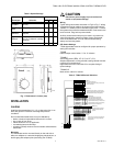
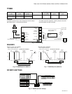
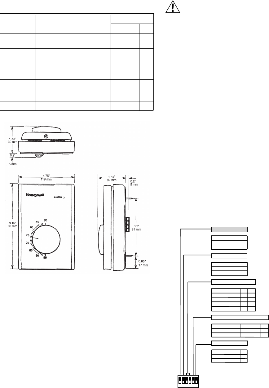
Fig. 1. Dimensions in inches (mm)
INSTALLATION
Location
Install the thermostat about 5 ft. (1.5 m) above the floor in an
area with good air circulation at average temperature
conditions.
Do not install thermostat where it may be affected by:
• drafts, or dead air spots behind doors and in corners.
• hot or cold air from ducts.
• radiant heat from sun or appliances.
• concealed pipes and chimneys.
• unheated (cooled) areas such as an outside wall behind the
thermostat.
Mounting
The thermostat can be mounted directly on the wall with or
without a wallplate or a standard single gang electrical box, or
double gang with adaptor plate (accessory part 272846).
CAUTION
Disconnect power supply to prevent electrical
shock or equipment damage.
Wiring
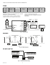
Typical wiring connections are shown in Fig.2 to Fig.7. Wiring
connections may be made to the screw terminal block with 2-
18AWG or 1-14AWG, solid or stranded copper wires. Connect
the system wires to the thermostat terminals. Push excess wire
back into hole. Plug hole to prevent drafts.
Auxiliary screw terminal strip may be used in a junction box
when the application requires multiple wires to be brought
down at the thermostat. This can make troubleshooting,
startup and servicing easier.
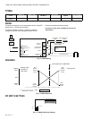
DIP Switch Settings
T7984 thermostats must be configured for proper operation by
setting DIP switches.
T7984B
Reheat output control action: 7.5 or 15 minutes.
T7984B,C
Zero energy band (ZEB): 3°F (2°C) or 5°F (3°C)
Setpoint adjustment: cooling,centred, heating centred with limit
override for commissioning.
Night setback amount: see Table 2 for complete listing of
option settings.
T7984A,B,C
Main sensor, internal or remote.
Table 3. T7984 DIP Switch Definition
OUTPUT 2 ON/OFF CPH
T7984B only
For more information, see on/off output cycle per hour application note.
CYCLES/HOUR S1
FAST 8 CPH 1
SLOW 4 CPH 0
It is possible to fix the number of times per hour the on/off
output will be energized.
ZERO ENERGY BAND T7984B & C only
ZEB S2
5°F (3°C) 1
3°F (1.5°C)
0
On models which have 2 outputs, 1 for cooling and 1 for
heating, it is possible to adjust the zero energy band value
(dead band between heating and cooling endpoints).
SETPOINT DIAL DEFINITION
T7984B & C only
For more information, see setpoint dial definition & setpoint limitation application note.
Models with cooling and heating outputs
» Setpoint dial centered, 75˚F limitation not active.
» Setpoint dial defined as heating, 75˚F limitation active.
DEFINITION S3
S4
75°F OVERRIDE
1 1
HEATING DIAL 0
1
COOLING DIAL
1 0
CENTERED HC
0 0
» Setpoint dial defined as cooling, 75˚F limitation active.
» Setpoint dial centered, 75˚F limitation active.
DAY/NIGHT SETBACK
T7984B & C only
HEAT SETBACK COOL SETUP
S5
10°F (5°C)
20°F (10°C)
1
5°F (3°C)
5°F (3°C)
0
Night mode setpoints can be adjusted
to different values depending on the
application.
REMOTE SENSOR T7984A, B & C
On model T7984A, switch S7 & S8 are not used.
MAIN SENSOR
LOCAL INTERNAL
REMOTE SENSOR
For duct return air or remote room sensor control only.
1
S6
Do not use remote sensor in supply or discharge air
0
control applications.
ON = 1
OFF = 0 1 2 3 4 5 6
3 95C-10815–2


