T7984 A,B,C ELECTRONIC MODULATING CONTROL THERMOSTATS
T7984C
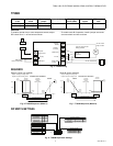
Output 1 analog
2œ10V
Output 2
analog 2œ10V
Mode input
jumper
Changeover input
for Out 1
Day/Night
mode (NSB)
Remote sensor
option
75°F setpoint
limit
Cooling and
Heating
Heating only X X X X
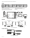
WIRING
To install a remote duct or room temperature sensor, adust DIP the screw terminals and wire as shown.
switch S6 to 0 = off and wire as shown.
(If sensor is used, wire 1changeover sensor per
To reverse operation of output 1 to heating, install the thermostat.)
changeover contact or the changeover sensor across
Duct
or
Room
NSB contact
from a central timer
NSB input
Remote
sensor input
(0 Vac)
Output 1
2-10 Vdc
Output 2
2-10 Vdc
Changeover
input for Out 1
24 Vac
Power supply
(0 Vac)
Changeover
contact
OR
Changeover
sensor
Input (2-10 Vdc)
24 Vac
Common
Input (2-10 Vdc)
24 Vac
Common
2-10 Vdc valve or VAV
analog actuator
24 Vac Transformer
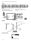
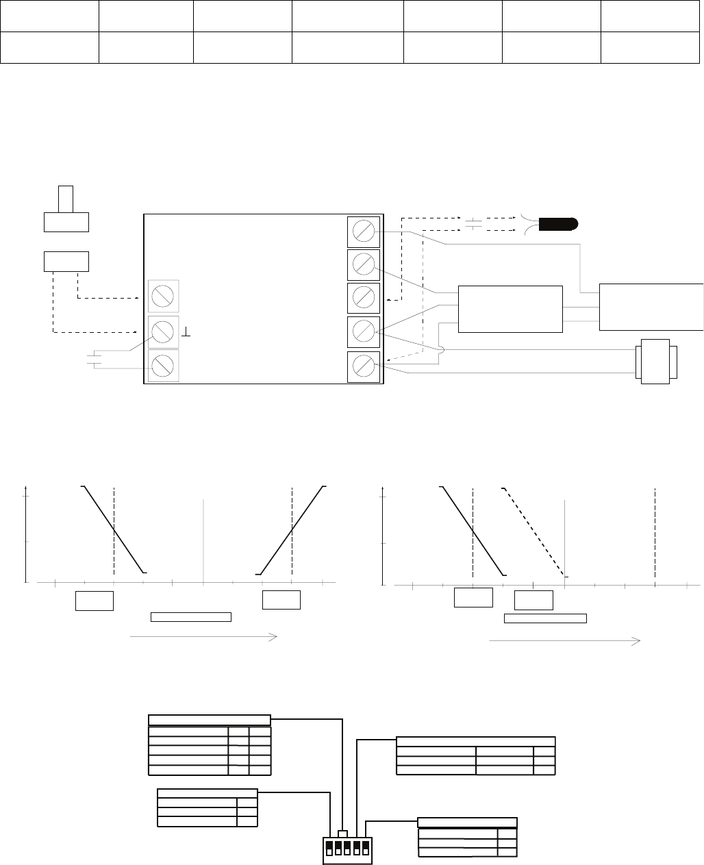
Fig. 9. T7984C Wiring
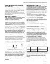
SEQUENCE
SETPOINT DIAL DEFINITION
SETPOINT DIAL DEFINITION
SETPOINT
SETPOINT
HEATING
COOLING
HEATING
COOLING
SETPOINT
CENTERED
SETPOINT
SETPOINT
CENTERED
End
End
Device
closed
2 Vdc
IN ZERO
ENERGY BAND
OUTPUT 2
ANALOG
OUTPUT 1
ANALOG
SETPOINT
End
IN ZERO
End
End
Device
Device
100%
ENERGY BAND
100%
Device
Device
opened
10 Vdc
50%
End
Device
closed
0%
OUTPUT 2
ANALOG
2 Vdc
opened
10 Vdc
opened
10 Vdc
opened
10 Vdc
50%
End
Device
closed
2 Vdc
0%
OUTPUT 1
ANALOG
End
Device
closed
2 Vdc
ZERO ENERGY BAND
ZERO ENERGY BAND
Temperature increase
Temperature increase
Fig. 10. T7984C Sequence
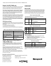
DIP SWITCH SETTING
DEFINITION S3
S4
75°F OVERRIDE
1 1
HEATING DIAL 0
1
COOLING DIAL
1 0
CENTERED HC
0 0
SETPOINT DIAL DEFINITION
ON = 1
HEAT SETBACK
10°F (5°C)
5°F (3°C)
COOL SETUP
20°F (10°C)
5°F (3°C)
S5
1
0
DAY/NIGHT SETBACK
ZERO ENERGY BAND
ZEB S2
5°F (3°C) 1
3°F (1.5°C)
0
REMOTE SENSOR
MAIN SENSOR S6
LOCAL INTERNAL 1
0
REMOTE SENSOR
OFF = 0
2 3 4 56
Fig. 11. T7984C Dip Switch Setting
95C-10815–2 6


