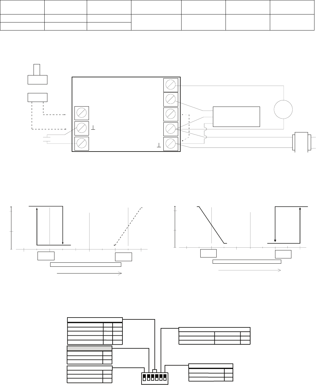
T7984 A,B,C ELECTRONIC MODULATING CONTROL THERMOSTATS
T7984B
Output 1 analog
2œ10V
Output 2
on/off
Mode input
jumper
Changeover input
for Out 1
Day/Night
mode (NSB)
Remote sensor
option
75°F setpoint
limit
Cooling Heating
Mode A (Jumper out)
X X X
Heating Cooling
Mode B (Jumper in)
WIRING
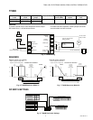
To install a remote duct or room temperature sensor, adjust * To enable mode B of operation, install a jumper across the
DIP switch S6 to 0 = off and wire as shown. screw terminals and wire as shown
Duct
or
NSB contact
from a central timer
SEQUENCE
Mode A (jumper not installed)
Output 1 analog in cooling mode
Output 2 on/off in heating mode
Room
Remote
sensor input
(0 Vac)
NSB input
SETPOINT DIAL DEFINITION
HEATING
End
SETPOINT
SETPOINT
Device
CENTERED
Output 2
On/off
Output 1
2-10 Vdc
Mode input
24 Vac
Power supply
(0 Vac)
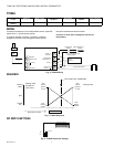
Fig. 5. T7984B Wiring
on
IN ZERO
Device
100%
ENERGY BAND
opened
10 Vdc
50%
Device
Device
closed
off
2 Vdc
0%
OUTPUT 2
ON/OFF
OUTPUT 1
ANALOG
ZERO ENERGY BAND
Temperature increase
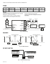
Fig. 6. T7984B Sequence (Mode A)
DIP SWITCH SETTINGS
DEFINITION S3
S4
75°F OVERRIDE
1 1
HEATING DIAL 0
1
COOLING DIAL
1 0
CENTERED HC
0 0
SETPOINT DIAL DEFINITION
ZEB S2
5°F (3°C)
3°F (1.5°C)
1
0
ZERO ENERGY BAND
CYCLES/HOUR S1
FAST 8 CPH 1
SLOW 4 CPH 0
OUTPUT 2 ON/OFF CPH
ON = 1
123 4 56
OFF = 0
COOLING
SETPOINT
End
Input (2-10 Vdc)
24 Vac
Common
2-10 Vdc valve or VAV
analog actuator
24 Vac on/off
relay or valve
24 Vac Transformer
R
Mode B (jumper installed)
Output 1 analog in heating mode
Output 2 on/off in cooling mode
SETPOINT DIAL DEFINITION
HEATING
Device
End
SETPOINT
CENTERED
SETPOINT
opened
IN ZERO
Device
100%
10 Vdc
ENERGY BAND
on
50%
Device
closed
Device
2 Vdc
off
0%
OUTPUT 2
ON/OFF
ZERO ENERGY BAND
Temperature increase
OUTPUT 1
ANALOG
Fig. 7. T7984B Sequence (Mode B)
HEAT SETBACK
10°F (5°C)
5°F (3°C)
COOL SETUP
20°F (10°C)
5°F (3°C)
S5
1
0
DAY/NIGHT SETBACK
REMOTE SENSOR
MAIN SENSOR S6
LOCAL INTERNAL 1
0
REMOTE SENSOR
COOLING
SETPOINT
End
Fig. 8. T7984B Dip Switch Settings
5 95C-10815–2


