


T4800A PRECISION ELECTRONIC ELECTRIC HEATING THERMOSTAT
68-0151—1
3
MERCURY NOTICE
If this control is replacing a control that contains
mercury in a sealed tube, do
not
place your old
control in the trash.
Contact your local waste management authority for
instructions regarding recycling and the proper
disposal of your old control.
INSTALLATION
When Installing this Product…
1. Read these instructions carefully. Failure to follow these
instructions could damage the product or cause a
hazardous condition.
2. Check the ratings on the product to make sure the
product is suitable for your application.
3. Installer must be a trained, experienced service
technician.
4. After installation is complete, check out product
operation as provided in these instructions.
WARNING
HIGH VOLTAGE CONTROL.
ELECTRICAL SHOCK HAZARD.
Follow local codes and ordinances when installing this
thermostat. Improper handling may cause serious
injury or death.
CAUTION
1. Disconnect power supply to prevent electrical
shock or equipment damage.
2. If connecting with aluminum conductors, use
CO/ALR solderless wire connectors to avoid fire
hazard.
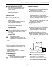
Location
Install a vertical outlet box, which is used to mount the
thermostat on, about 5 ft (1.5m) above the floor in an area
with good air circulation at room temperature.
Do not install the thermostat where it may be affected by:
— drafts or dead spots behind doors, in corners or under
cabinets.
— hot air from convectors.
— radiant heat from sun or appliances.
— concealed pipes and chimneys.
— unheated (uncooled) areas such as an outside wall
behind the thermostat.
Wiring and Mounting
CAUTION
1. Handle the thermostat with care to avoid damage.
2. Use a separate limit control in the heating
appliance.
3. Do not short 208 or 240 volt supply wires with
thermostat. This will damage the T4800 and void
the warranty.
Replacement Applications
³ Disconnect power to the thermostat to prevent electrical
shock or equipment damage. All wiring must comply
with local electrical codes and ordinances.
· Remove the old thermostat from the wall, taking care
not to damage the wiring insulation.
» Check the old wire insulation for cracks, nicks or
fraying. Apply approved electrical tape to insulate wires
or replace wires as necessary.
¿ Carefully remove thermostat cover by gently lifting at
top edge with a flathead screwdriver. Using wire
connectors approved for No. 12 wires, make line
voltage connections directly to leadwires on thermostat.
See Fig. 2 for typical wiring connections. Be sure all
wiring connections are tight.
´ Prebend and push solid wires into the outlet box.
² Secure the thermostat on the outlet box by tightening
the two mounting screws. (Rotate control knob to more
easily access lower mounting screw.)
¶ Snap thermostat cover in place.
New Applications
³ Disconnect power to the thermostat to prevent electrical
shock or equipment damage. All wiring must comply
with local electrical codes and ordinances.
· Carefully remove thermostat cover by gently lifting at
top edge with a flathead screwdriver. Using wire
connectors approved for No. 12 wires, make line
voltage connections directly to leadwires on thermostat.
See Fig. 2 for typical wiring connections. Be sure all
wiring connections are tight.
» Prebend and push solid wires into the outlet box.
¿ Secure the thermostat on the outlet box by tightening
the two mounting screws. (Rotate control knob to more
easily access lower mounting screw.)
´ Snap thermostat cover in place.
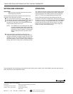
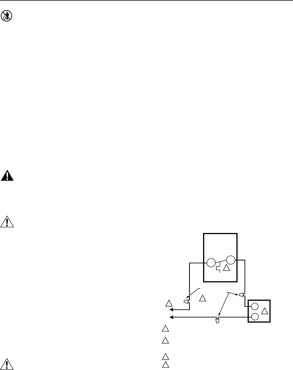
M7103
L1
(HOT)
L2
L1
T1
1
2
4
3
SOLDERLESS
CONNECTORS
POWER SUPPLY. PROVIDE DISCONNECT MEANS AND
OVERLOAD PROTECTION AS REQUIRED.
USE SPECIAL SERVICE CO/ALR SOLDERLESS CONNECTORS
WHEN CONNECTING ALUMINUM CONDUCTORS OR A FIRE
HAZARD MAY RESULT.
BREAKS HEATING CIRCUIT ON A TEMPERATURE RISE.
USE A SEPARATE LIMIT CONTROL IN THE HEATING APPLIANCE.
1
2
3
4
T4800A
ELECTRIC
HEATER
BLACK
BLACK
Fig. 2. Typical wiring connections for T4800A.