95C-10903-1
T451, T651 MOTOR-RATED PRECISION THERMOSTATS INSTALLATION
WHEN INSTALLING THIS PRODUCT:
1. Read these instructions carefully. Failure to follow
instructions can damage product or cause a hazardous
condition.
2. Check ratings given in instructions and on product to
make sure product is suitable for your application.
3. Make sure installer is a trained, experienced service
technician.
4. After completing installation, use these instructions to
check out product operation.
!
WARNING
This thermostat is a line voltage (120 to 277 Vac)
control. Do not install it unless you are completely
familiar and competent with home wiring.
If improperly handled there can be a risk of
240 volt electric shock hazard which may cause
serious injury or death.
!
CAUTION
1. Disconnect power supply before making wiring
connections to prevent electrical shock or equipment
damage.
2. All wiring must comply with national and local codes
and ordinances.
3. When using aluminum conductors, all wiring connec-
tions to this thermostat must be made to the factory
installed leadwires using approved CO/ALR solderless
connectors. A fire hazard may result otherwise.
4. To avoid handling the sensing element, do not remove
thermostat cover until wiring is completed.
5. Thermostats are designed for use with appliances
having a limit control.
New Installations
1. Install a single-gang electrical box oriented vertically about
4’ to 5’ (1.5 m) above the floor on an inside wall or pillar
where the thermostat will be subjected to typical room
temperature.
NOTE: To sense temperature properly, the thermostat
must be placed away from concealed warm or cold water
pipes, air ducts, or drafts from hallways, fireplaces or
stairways. Do not place thermostat above convectors or
in the flow from supply fans. Ideally, a thermostat should
be close to the return air path to effectively measure
average room temperature.
2. Wire installation in an approved fashion.
NOTE: T651A and T451A do not feature a Positive Off
setting, and may not be used as a disconnect switch.
3. Leave cover on the thermostat while making wiring
connections. Use solderless connectors approved for the
type, number and gauge of wires being joined.
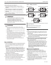
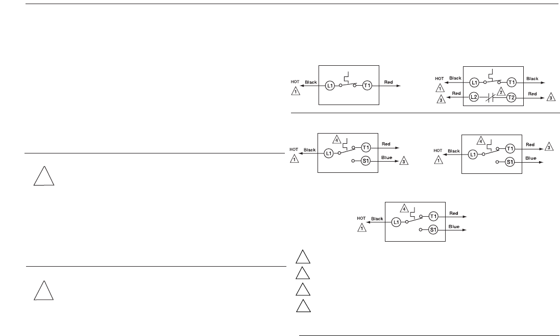
Connect as per Fig. 2 for the appropriate application.
Fig. 2 — Wiring connections
4. Pre-bend and push leadwires into the electrical junction
box.
5. Hold the thermostat base with one hand and remove the
thermostat cover by grasping two sides of the cover and
pulling outward.
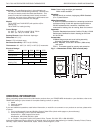
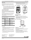
NOTE: If locking cover feature is desired, insert the locking
cover clip in the thermostat base BEFORE mounting the
thermostat on the wall (see Fig. 7).
6. Using the screwdriver, secure the thermostat to the box by
tightening the two mounting screws. Handle thermostat
with care. Excessive pressure may damage the control
knob or sensing element.
IMPORTANT: Before mounting the thermostat, turn the
setting dial to the mid-position (indicator pointing to the
top of the thermostat): this will prevent damage to the
dial stop if the dial is accidentally turned by the screw
driver when the top mounting screw is tightened. Do
NOT press on diaphragm, diaphragm lever arm or
setpoint knob to seat thermostat on the box: thermostat
will be damaged.
Replacement Applications
1. Disconnect power supply before making wiring
connections to prevent electrical shocks or equipment
damage. All wiring must comply with applicable codes
and standards.
2. Remove the old thermostat from the wall, taking care not
to damage the wiring insulation.
3. Check the old insulation for cracks, nicks or fraying. Apply
certified electrical tape where necessary to insulate wires,
or replace the wires in an approved fashion.
4. Complete installation following steps 3 to 6 in the New
Installations section.
3
T451A (Heat only)
To
Heating
Load
To
Heating
Load
To
Heating
Load
T651A (Heat only)
T651A (Heat–Cool application)
To
Cooling
Load
T651A (Cool only application)
To
Cooling
Load
To
Heating
Load
T451B (Heat only with positive off)
1 Power supply; provide disconnect means and overload protection as required.
2 Breaks on Positive Off.
3 Exposed unused wires must be properly insulated.
4 Contact makes Black to Red on temperature fall;
Black to Blue on temperature rise.


