


5 60-2241—8
T4039A,B,D-M,S,V
INSTALLATION
Installation
WHEN INSTALLING THIS PRODUCT…
1. Read these instructions carefully. Failure to follow
them could damage the product or cause a hazardous
condition.
2. Check the ratings given in the instructions and on
the product to make sure the product is suitable for your
application.
3. Installer must be a trained, experienced service
technician.
4. After the installation is complete, check out product
operation as provided in these instructions.
CAUTION
Disconnect power supply to prevent electrical shock
or equipment damage.
Before mounting, be sure to remove cardboard shipping
inserts that protect the contacts.
1. Remove T4039 cover by loosening the cover screw
with Allen wrench.
2. Open the cardboard inside cover by pressing inward on
the left side to release latch. Do not remove this cover.
3. Carefully remove the shipping inserts from around the
snap contacts.
4. Check contact operation before mounting device.
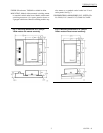
MOUNTING
Models without manual switching mount on standard
vertical outlet boxes. Models with manual switching
mount on 4-in. square junction boxes or 2-ganged outlet
boxes. Manual switching models can also mount on stan-
dard vertical outlet boxes if local electrical codes permit.
Mount thermostat on side wall about 5 ft. [1.5 m] above
the floor. Do not mount where thermostat can be affected by
drafts, radiant heat from the sun or other sources of heat.
Use Allen wrench to open cover and mount according
to Fig. 3. Two mounting screws are provided.
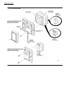
WIRING
Disconnect power supply before beginning installa-
tion to avoid electrical shock or equipment damage. All
wiring must comply with local codes and ordinances.
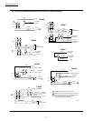
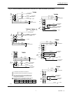
Internal schematic and external connections for the
T4039 are shown in Fig. 4. Use solderless connectors or
other approved methods to wire thermostat into the sys-
tem. Six-inch color-coded leadwires are provided.
SETTING
The T4039 temperature scale is marked COOL-WARM
with approximate scale divisions of 10° F from 75° F
[24° C] midpoint. The range is approximately 55° F to 95°
F [13° C to 35° C]. Set lever at desired temperature.
To adjust the temperature setpoint range stops, Fig. 3,
locate stops at the desired temperature range setpoint
and insert.