


4
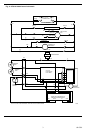
ST9141A1002 Operating Sequence
Action System Response
Thermostat calls for heat. • Pressure switch confirmed in no airflow position. (If pressure switch shows
(W terminal is energized.) airflow, LED flashes three times.)
• Combustion air blower is energized.
• Air proving switch makes (air flow is established).
• Ignition system is energized.
• Gas valve opens and main burner lights.
• Heat fan on delay timing begins. When timing is complete, circulating blower
is energized at heat speed.
Thermostat ends call for heat. • Ignition system is de-energized and gas valve closes.
(W terminal is de-energized.) • Combustion air blower is de-energized after postpurge timing.
• Heat fan off delay timing begins. When timing is complete, the circulating fan
is de-energized.
Thermostat begins call for cool. • Cooling contactor is energized.
(G and Y terminals are energized.) • Circulating fan is energized at cool speed after cool fan on delay timing.
Thermostat ends call for cool. • Cooling contactor is de-energized.
(G and Y terminals are de-energized.) • Circulating fan turns off after cool fan off delay timing.
Thermostat begins call for fan. • Circulating fan is energized at heat speed two seconds after G terminal is
(G terminal is energized.) energized.
• If a call for heat occurs, circulating fan continues to run at heat speed.
• If a call for cool occurs, circulating fan switches to cool speed after four-
second delay.
Thermostat ends call for fan. • Circulating fan is de-energized.
(G terminal is de-energized.)
Primary limit switch string opens. • Thermostat and ignition system are de-energized and gas valve closes.
• Combustion air blower is de-energized.
• Circulating fan is energized at heat speed.
• LED flashes twice.
• If there is a call for cooling or fan, the circulating fan switches from heat speed
to cool speed.
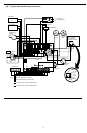
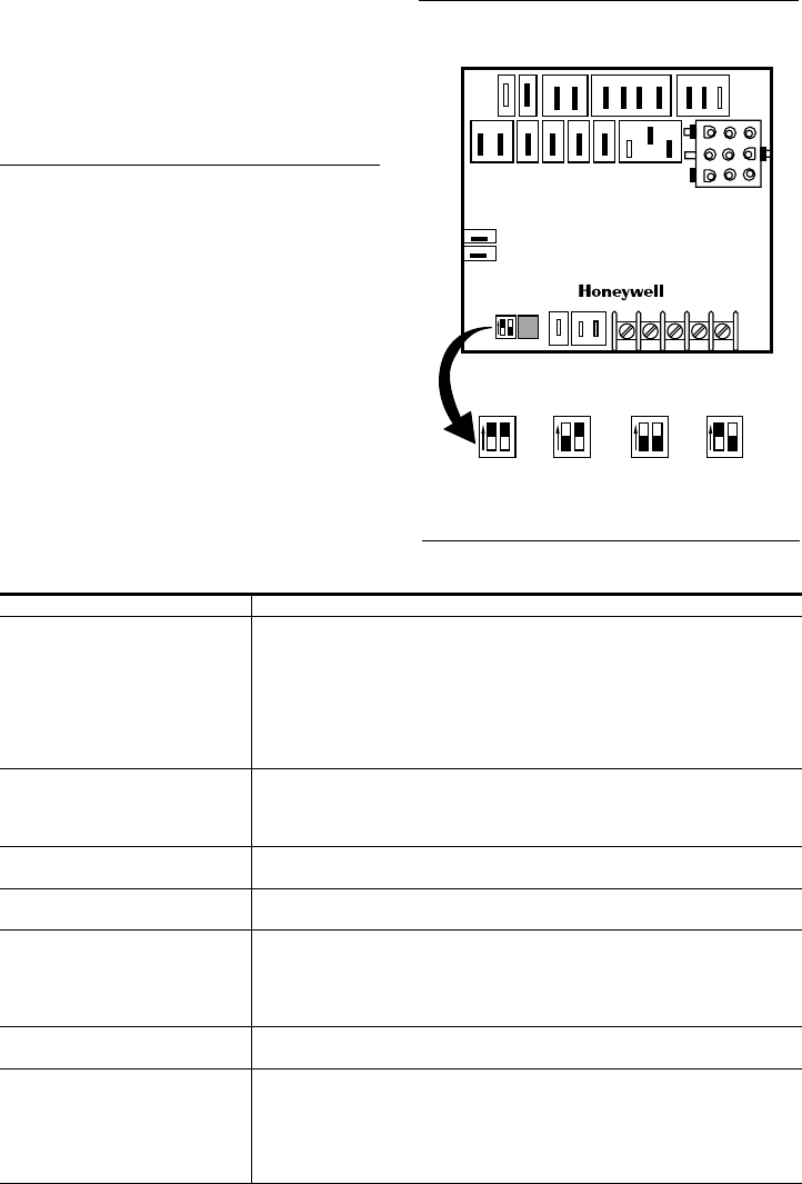
Setting the Heat Fan Off Delay DIP Switches
Set the heat fan off delay DIP switches to 60, 100, 140 or
180 seconds as shown in Fig. 3. The off delay is factory-set
at 140 seconds. This delay time starts when the main gas
valve is de-energized at the end of a thermostat call for heat.
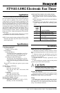
Checkout
Assure the system operates properly by operating the
system through at least one complete heating cycle and
cooling cycle. Troubleshoot by checking for appropriate
voltages at the ST9141A1002 terminals controlling the
combustion air blower and heat and cool speed circulating
fan. The ST9141A1002 schematic shows internal switch-
ing to clarify operation and assist in troubleshooting. See
Fig. 2.
Fig. 3—Setting delay off DIP switches.
60 SECONDS 100 SECONDS
140 SECONDS
180 SECONDS
M5658
DELAY OFF DIP SWITCH SETTINGS
1
2
1
2
1
2
1
2
ON
OFF
UNUSED
G
W
C
Y
R
CY
1
2
UP
SPEED
DELAY
OFF
Z1
Z2
12
3 DI
1
2
3
4
N
MOTOR
LEADS
CX
XFMR
SEC
X
EAC N
HUM N
CIR
BLWR
CONT
COOL
HEAT
ST9141
NEUTRAL
(continued)