


13 69-0463
TRIAL FOR IGNITION
Pilot Ignition
Following prepurge timing (S8660, S8670), or on the call
for heat (S8600, S8610), the module energizes the first
main valve operator. The first main valve opens, which
allows gas to flow to the pilot burner. At the same time, the
electronic spark generator in the module produces an over
10,000 volt spark pulse output. The voltage generates a
spark at the igniter (S8600A,B; S8610A,B) or igniter-sensor
(S8600F,H,M; S8610F,H; S8660; S8670) that lights the
pilot.
If the pilot does not light, or the pilot flame current is not
at least 1.0 µA and steady, the module will not energize the
second (main) valve and the main burner will not light.
S8600A,F; S8610A,F will continue to spark as long as the
thermostat calls for heat, or until the pilot lights.
Safety Lockout (S8600B,H; S8610B,H; S8660D; S8670D)
These modules provide 100 percent shutoff and safety
lockout. A timer in these models starts timing the moment
the trial for ignition starts. Ignition spark continues only until
the timed trial for ignition period ends. Then the module
goes into safety lockout. Lockout de-energizes the first
main valve operator and closes the first main (pilot) valve in
the gas control, stopping pilot gas flow. The control system
must be reset by setting the thermostat below room tem-
perature for one minute or by turning off power to the
module for one minute.
Safety Shutoff with Continuous Retry (S8600M)
The S8600M provides 100 percent gas shutoff, followed
by retry for ignition. Operation on ignition failure is the same
as lockout modules, except that a timer starts timing imme-
diately following shutoff. Six minutes nom. (five minutes
min.) after shutoff, the module restarts the ignition se-
quence. The ignition trial, shutoff, wait sequence continues
until either the pilot lights or the thermostat is set below
room temperature to end the call for heat. The module can
also be reset by setting down the thermostat for one minute.
MAIN BURNER OPERATION
When the pilot flame is established, a flame rectification
circuit is completed between the sensor and burner ground.
The flame sensing circuit in the module detects the flame
current, shuts off the spark generator and energizes the
second main valve operator. The second main valve opens
and gas flows to the main burner, where it is ignited by the
pilot burner. On lockout models, the flame current also
holds the safety lockout timer in the reset (normal) operat-
ing condition.
When the call for heat ends, both valve operators are de-
energized, and both valves in the gas control close.
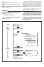
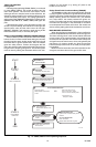
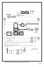
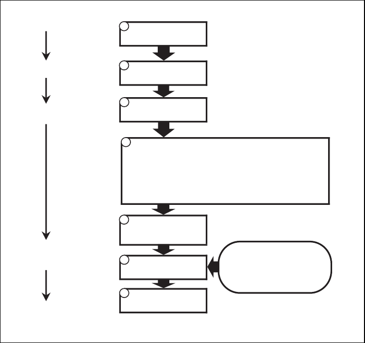
Fig. 12—S8660, S8670 normal operating sequence.
M1171B
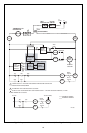
START
THERMOSTAT
PREPURGE
SPARK GENERATOR POWERED
PILOT BURNER OPERATION
OR
Pilot burner lights.
S8660, S8670 senses flame
current.
Pilot burner does not light.
After 15 or 90 sec , system
locks out; must be manually reset.
Lockout timing is
stamped on module.
a
a
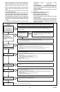
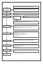
STAGE 1
PREPURGE
STAGE 2
TRIAL FOR IGNITION
STAGE 3
MAIN BURNER
OPERATION
END
FLAME CURRENT SENSED
MAIN BURNER OPERATION
Module monitors pilot flame
current.
THERMOSTAT SATISFIED
Valves close, pilot and main
burners are off.
POWER INTERRUPTION
System shuts off, restarts when power is
restored.
PILOT FLAME FAILURE
Main valve closes.
S8660, S8670 starts trial for ignition.
Spark generator off.
Second valve operator (main)
opens.
1
2
3
4
5
6
7
CALLS FOR HEAT
Combustion air blower starts.
First valve (pilot) operator opens.