


RM7800E,G,L,M; RM7840E,G,L,M 7800 SERIES RELAY MODULES
11 66-1085—04
g. Lockout Interlock opens during PREPURGE
(RM7840E,L).
h. Ignition/pilot valve/intermittent pilot valve terminal is
energized.
i. Main valve terminal is energized.
j. Internal system fault occurred.
k. Purge card is removed.
l. Purge card is bad.
4. PILOT FLAME ESTABLISHING Period (PFEP):
a. Low Fire Switch opens.
b. Lockout Interlock opens (RM7840E,L).
c. Ignition/pilot valve/intermittent pilot valve terminal is
not energized.
d. Early spark termination terminal is energized after
five seconds.
e. No flame is present at the end of PFEP.
f. Main valve terminal is energized (RM7800G,M).
g. Internal system fault occurred.
h. Purge card is removed.
i. Purge card is bad.
5. MAIN FLAME ESTABLISHING Period (MFEP):
a. Low Fire Switch Opens.
b. Lockout Interlock opens (RM7840E,L).
c. Ignition/pilot valve/intermittent pilot valve terminal is
not energized.
d. Main valve terminal is not energized.
e. No flame is present at the end of MFEP.
f. Internal system fault occurred.
g. Purge card is removed.
h. Purge card is bad.
6. RUN Period:
a. No flame is present.
b. Lockout Interlock opens (RM7840E,L).
c. Interrupted pilot valve terminal is energized
(RM7840G,M).
d. Main valve terminal is not energized.
e. Internal system fault occurred.
f. Purge card is removed.
g. Purge card is bad.
7. POSTPURGE Period:
a. Preignition Interlock does not close in five seconds
and opens after five-second time period.
b. Ignition/pilot valve/intermittent pilot valve terminal is
energized.
c. Main valve terminal is energized.
d. Internal system fault occurred.
e. Purge card is removed.
f. Purge card is bad.
OPERATION
Sequence of Operation
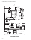
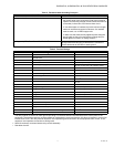
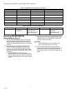
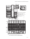
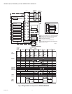
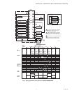
The RM7800/RM7840 has the following operating sequences,
see Fig. 2, 3, 4, and Table 6. The RM7800/RM7840 LED
provide positive visual indication of the program sequence:
POWER, PILOT, FLAME, MAIN and ALARM.
Initiate
The RM7800/RM7840 enters the INITIATE sequence when
the Relay Module is powered. The RM7800/RM7840 can also
enter the INITIATE sequence if the Relay Module verifies
voltage fluctuations of +10/-15 percent or frequency
fluctuations of +/-10 percent during any part of the operating
sequence. The INITIATE sequence lasts for ten seconds
unless the voltage or frequency tolerances are not met. When
the tolerances are not met, a hold condition is initiated and
displayed on the VFD for at least five seconds. When the
tolerances are met, the INITIATE sequence restarts. If the
condition is not corrected and the hold condition exists for four
minutes, the RM7800/RM7840 locks out. Causes for hold
conditions in the INITIATE sequence:
a. AC line dropout is detected.
b. AC line noise prevents a sufficient reading of the
line voltage inputs.
c. Low line voltage brownouts occur.
The INITIATE sequence also delays the burner motor starter
from being energized and de-energized from an intermittent
AC line input or control input.
Standby
The RM7800/RM7840 remains in standby, ready to start. The
operating control determines a call for heat is present and
provides input to terminal 6. The burner switch, limits,
operating control and all microcomputer monitored circuits
must be in the correct state for the RM7800/RM7840 to
advance into the PREPURGE sequence.
Prepurge
The RM7800/RM7840 provides a prepurge timing selectable
from two seconds to 30 minutes with power applied and the
RM7800 operating control indicating a call for heat:
a. Running Interlocks, Preignition Interlocks, Burner
Switch, Run/Test Switch, Lockout Interlocks and all
microcomputer monitored circuits must be in the
correct operating state.
b. The blower motor output, terminal 5, is powered to
start the PREPURGE sequence, except for the
RM7800E/RM7840E. The firing rate motor is driven
to the high fire position. The PREPURGE timing for
the RM7800/RM7840E,L does not begin until the
Lockout Interlock String and High Fire Switch are
both closed. The blower motor output for the
RM7800E is not energized until the High Fire Switch
is closed.
c. The Preignition Interlock input must remain closed
throughout PREPURGE; otherwise, control returns
to the STANDBY state and holds (30 seconds) for
the RM7800/RM7840G,M or safety shutdown for the
RM7800/RM7840E,L occurs.
d. The Lockout Interlock or Running Interlock inputs
(interlock circuit including Airflow Switch) must close
by ten seconds into PREPURGE; otherwise, a
recycle to the beginning of PREPURGE for the
RM7800/RM7840G,M will happen or a safety
shutdown for the RM7800/RM7840E,L occurs.
e. When PREPURGE timing is complete, the firing rate
motor drives to the low fire position,
RM7800/RM7840E,G,L.
f. When the firing rate motor reaches low fire position,
the Low Fire Switch, terminal 18, input must be
energized before entering the Ignition Trial state.
Ignition Trials
1. Pilot Flame Establishing Period (PFEP):
a. With the firing rate motor at the low fire position:
(1) The pilot valve and ignition transformer,
terminals 8, 10 and 21, are energized. The
RM7800M has an intermittent pilot valve,