R8182D,E,F,H,J COMBINATION PROTECTORELAY™ AND HYDRONIC HEATING CONTROLS
68-0105—2 6
NOTE: Do not make sharp bends in the tubing. A sharp
bend can break the tubing and cause a loss of fill. In
models with an adjustable tubing length, pull the
extra tubing out of the controller case.
d. Fit the controller case onto the immersion well so
that the immersion well clamp slides over the flange
of the immersion well.
e. Securely tighten the immersion well clamp screw.
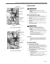
6. For R8182H,J models:
a. Loosen the screw holding the hinged backplate to
the controller case and swing the backplate away
from the controller case.
b. Screw the backplate to a 4 by 4 inch junction box.
c. Insert the bulb into the immersion well until it
bottoms.
d. If necessary, bend the capillary tube to hold the bulb
against the bottom of the immersion well.
NOTE: Do not make sharp bends in the tubing. A sharp
bend can break the tubing and cause a loss of fill. In
models with an adjustable tubing length, pull the
extra tubing out of the controller case.
e. Tighten the immersion well screw over the brass
collar.
f. After wiring, swing control against the backplate and
refasten with the screw.
7. Refill the boiler and check for water leakage.
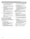
Mounting the R8182D TRADELINE®
If the existing immersion well does not fit the R8182D
immersion well clamp, use a 1249094 immersion well adapter
(order separately; see form 68-0040, Wells and Fittings for
Temperature Controllers).
1. Disconnect the power supply.
2. Drain all water from the boiler.
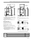
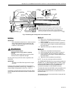
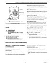
3. Fasten the R8182D immersion well clamp to the flange
on the immersion well adapter. Refer to Fig. 9.
4. Place the adapter on the capillary tube.
5. Put the adapter end into the hole in the controller case
and tighten the clamp screw.
6. Insert the sensing bulb into the immersion well and
bend the capillary tubing, if necessary, to hold the
sensing bulb against the bottom of the immersion well.
NOTE: Do not make sharp turns while bending the capillary
tubing. In models with an adjustable tubing length,
pull the extra tubing out of the controller case.
7. Apply the heat-conductive compound into the
immersion well (if necessary).
a. Fold the plastic bag of heat-conductive compound
lengthwise and twist it gently.
b. Cut off the end of the plastic bag and work the open
end of the bag all the way into the immersion well.
c. Slowly pull the bag out of the immersion well while
squeezing it firmly to evenly distribute the
heat-conductive compound.
8. Wipe off any excess grease and tighten the set screw
against the adapter.
If the existing immersion well is not usable, remove the
existing immersion well and order a new one using form
68-0040, Wells and Fittings for Temperature Controllers.
1. Disconnect the power supply.
2. Drain all water from the boiler.
3. Install the new immersion well by threading it into the
threaded hole.
4. Loosen the immersion well clamp screw. See Fig. 9.
5. Insert the sensing bulb into the immersion well and
bend the capillary tubing, if necessary, to hold the
sensing bulb against the bottom of the immersion well.
NOTE: Do not make sharp turns while bending the capillary
tubing. In models with an adjustable tubing length,
pull the extra tubing out of the controller case.
6. Apply heat-conductive compound into the immersion
well (if necessary).
a. Fold the plastic bag of heat-conductive compound
lengthwise and twist it gently.
b. Cut off the end of the plastic bag and work the open
end of the bag all the way into the immersion well.
c. Slowly pull the bag out of the immersion well while
squeezing it firmly to evenly distribute the
heat-conductive compound.
7. Be sure the immersion well fits the hole in the controller
case.
8. Position the immersion well clamp snugly over the
immersion well flange. Securely tighten the clamp
screw.
9. Refill the boiler and check for water leakage.


