


R8182D,E,F,H,J COMBINATION PROTECTORELAY™ AND HYDRONIC HEATING CONTROLS
68-0105—2 14
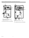
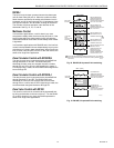
Fig. 20. R8182F Aquastat® limit switching.
STARTUP AND CHECKOUT
WARNING
Explosion Hazard.
Can cause severe injury, death or property
damage.
This product is intended for use only in systems with a
pressure relief valve.
Because heating systems differ, the correct temperature
setting for one system may not be correct for another. Follow
the boiler manufacturers recommendations for proper
selection of settings.
High Limit Setting—All Models
The high limit opens and turns off the burner when the water
temperature reaches the setpoint. The high limit automatically
resets after the water temperature drops past the setpoint and
through the 10°F (6°C) [15°F (8°C) with R8182E,J] differential.
Set the indicator at the desired shutoff temperature.
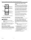
Low Limit/Circulator Setting—D And H
Models
On a temperature rise, with the adjustable differential at the
minimum setting of 10°F (6°C), the burner circuit (R-B) breaks
and the circulator circuit (R-W) makes at the low limit setpoint.
See Fig. 19. On a temperature drop of 10°F (6°C) below the
setpoint, the R-B circuit makes and the R-W circuit breaks.
At any differential setting greater than 10°F (6°C), the R-B
make temperature and R-W break temperature remains the
same— setting minus 10°F (6°C). The R-B break and R-W
make temperature are the setpoint temperature plus the
difference between the differential setting and 10°F (6°C).
EXAMPLE: Setpoint of 140°F (60°C); differential set at 25°F
(14°C). On a temperature rise, R-B breaks and R-W makes at
155°F (68°C). On a temperature fall, R-B makes and R-W
breaks at 130°F (54°C).
Set the low limit indicator at the minimum temperature
recommended for domestic hot water supply. This setting
must be at least 20°F (11°C) below the high limit setting to
prevent one switch from locking out the other.
Set the differential the desired number of degrees.
Circulator Setting—F Models
Set the circulator indicator at the minimum water temperature
recommended for hydronic heating comfort.
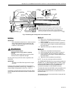
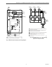
Setting Stops (R8182D,H TRADELINE®)
Part no. 126580 Setting Stops can be installed on the low and
high limit adjusting knobs to prevent turning the knobs beyond
a predetermined point. To install the setting stops, proceed as
follows:
IMPORTANT
Once the setting stops are in place, they cannot be
replaced. If they must be removed, cut off with
cutters—do not twist off.
1. On low limit knob, turn the knob to the setting that is to
be established as the limit.
2. Place the setting stop over the knob so that the arm of
the setting stop (after the stop is pressed into place)
strikes projection A and prevents turning the knob
beyond the chosen limit setting. See Fig. 21.
3. Press the setting stop tightly onto the knob so its inner
teeth securely engage the knob.
4. Turn knob back and forth several times to make sure
stop functions properly.
5. Repeat steps 1 to 4 for the high limit knob.
After settings are made, replace the cover.
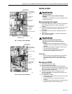
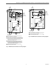
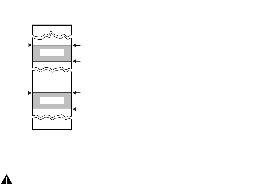
C
IRCULATOR
S
ETTING
H
IGH LIMIT
S
ETTING
R-B BREAKS ON
TEMPERATURE RISE.
BURNER TURNS OFF.
R-B MAKES ON
TEMPERATURE FALL.
BURNER OPERATES
ON CALL FOR HEAT.
R-B BREAKS ON
TEMPERATURE FALL.
CIRCULATOR TURNS OFF
.
R-W MAKES ON
TEMPERATURE RISE.
CIRCULATOR TURNS ON
.
110°F (43°C)
240°F (116°C)
M1509
10°F (6°C)
DIFFERENTIAL
10°F (6°C)
DIFFERENTIAL