


R7824, R7847, R7848, R7849,R7851,R7861, R7886 AMPLIFIERS FOR 7800 SERIES RELAY MODULES
65-0109—8 6
3. Disconnect power supply before making wiring
connections to prevent electrical shock and equipment
damage.
4. All wiring must comply with appropriate electrical codes,
ordinances and regulations including NEC Class 1 (Line
Voltage) wiring where required.
5. Use recommended wire size and type no. 18 copper
conductors TTW(60C) or THW (75C) or THNN(90C).
6. Use recommended wire routing:
a. Keep the flame signal leadwire as short as possible
from the detector to the 7800 SERIES Relay Module.
The maximum permissible leadwire length depends
on the type of leadwire, conduit type and leadwire
diameter. The ultimate limiting factor for flame signal
leadwire length is the flame signal voltage.
b. Do not run high voltage ignition transformer wires in
the same conduit with the flame detection wiring.
c. If the flame detector leadwires are not long enough
to reach the 7800 SERIES Relay Module electrical
connectors, make splices in a junction box.
(1) Enclose scanner wiring without armor cable in
metal cable or conduit.
(2) Follow flame detector Instructions.
7.
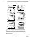
Check wiring, see Fig. 4.
8. Install 7800 SERIES Relay Module.
9. Restore power to the 7800 SERIES Relay Module.
Flame detector wiring is shown in Fig. 3.
CHECKOUT
Preliminary Inspection
Make certain that:
1.
Wiring connections are correct and all terminal screws
and electrical connections are tight.
2. Proper flame failure response time is selected.
3.
Amplifier is securely mounted on the 7800 SERIES
Relay Module.
4.
Detectors are properly positioned and cleaned
according to Detector Instructions.
5. Correct combination of amplifier and flame detector is
used.
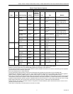
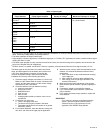
Flame Signal Measurement (Fig. 4)
Flame signal can be measured at the Flame Signal Test
Jacks, see Fig. 4, and at the Keyboard Display Module.
Measure the flame signal at the appropriate times defined in
the Checkout section; see applicable 7800 SERIES Relay
Module Instructions. See Table 3 for acceptable and
maximum flame signal voltage strengths.
CAUTION
Equipment Damage Hazard.
Improper wiring can destroy ultraviolet sensing
tube.
Carefully follow polarity sensitive wiring instructions for
the C7027, C7035, C7044, C7012, C7024, C7061,
C7961 and C7076. Reversing the leadwires, even
momentarily, can destroy the ultraviolet sensing tube.
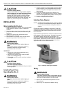
Fig. 4. Flame signal measurement with meter.
1.
Connect blue leadwire from detector to terminal F and
white leadwire from C7027/C7035/C7044/C7061 to
terminal G.
2.
Connect blue leadwire from detector to terminal F and
yellow leadwire from C7012/C7024/C7961 to terminal
G.
3. Follow lightoff Instructions for applicable 7800 SERIES
Relay Module.
Measuring Flame Signal With Keyboard
Display Module
Consult Instructions for applicable 7800 SERIES Relay
Module or Keyboard Display Module.
Measuring Flame Signal with a Volt
Ohmmeter
Two test jacks, positive and negative (Com) are accessible on
the top of the amplifier when plugged into the 7800 SERIES
Relay Module. These jacks are provided for monitoring flame
signal strength. Use a one megohm/volt meter to measure the
flame signal strength. Connect the positive meter lead (red) to
the positive (+) amplifier test jack and the negative meter lead
(black) to the negative (-) amplifier test jack. The test jacks
use standard 0.180 inch diameter voltmeter probes. A
minimum 1.25 Vdc flame signal is required.
NEGATIVE (-)
METER LEAD
POSITIVE (+)
METER LEAD
ONE
MEGOHM/VOLT
METER
M11459A
FLAME SIMULATOR
TEST JACK