


69-0931—3
3
Q7100A,C,D THERMOSTAT SUBBASES
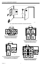
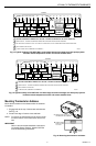
Fig. 6. Nine T7047C Sensors providing a
temperature averaging network for a
T7100/Q7100 Thermostat/Subbase.
Subbase Installation
The subbase can be mounted horizontally on the wall or
a 2 in. x 4 in. wiring box. Position the subbase horizon-
tally on the wall or on a 2 in. x 4 in. wiring box.
1. Position and level the subbase (for appearance
only). The thermostat will function properly even
when not level.
2. Use a pencil to mark the mounting holes. See Fig. 7.
3. Remove the subbase from the wall and drill two
3/16 inch holes in the wall (if drywall) as marked. For
firmer material such as plaster or wood, drill two
7/32 inch holes. Gently tap anchors (provided) into
the drilled holes until flush with the wall.
4. Position the subbase over the holes, pulling wires
through the wiring opening.
5. Loosely insert the mounting screws into the holes.
6. Tighten mounting screws.
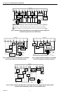
WIRING
All wiring must comply with local electrical codes and
ordinances. Refer to Fig. 9 through 15 for typical
hookups. A letter code is located near each terminal for
identification.
CAUTION
Disconnect power before wiring to prevent
electrical shock or equipment damage.
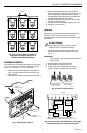
1. Loosen the terminal screws on the back of the
thermostat and connect the system wires. See
Fig. 8.
IMPORTANT
Use 18 gauge, color-coded thermostat cable for
proper wiring.
2. Securely tighten each terminal screw.
3. Push excess wire back into the hole.
4. Plug the hole with nonflammable insulation to
prevent drafts from affecting the thermostat.
M4842
TT
TT
SUBBASE
T7047C
TT
T7047C
TT
T7047C
TT
T7047C
TT
T7047C
TT
T7047C
TT
T7047C
TT
T7047C
TT
T7047C
WIRES
THROUGH WALL
WALL
LEDS
MOUNTING
HOLES
MOUNTING
SCREWS
M6531
WALL
ANCHORS
(2)
Fig. 7. Mounting the subbase.
Fig. 8. Proper wiring technique.
POWER SUPPLY. PROVIDE DISCONNECT MEANS
AND OVERLOAD PROTECTION AS REQUIRED.
1
1
L1
(HOT)
L2
M4831A
HEAT
RELAY OR
VALVE COIL
COMPRESSOR
CONTACTOR
RCOG
X
W
COOL
DAMPER
SUBBASE
B
HEAT
DAMPER
Y
FAN
RELAY
RH
M4826
FOR WRAPAROUND
INSERTION STRIP
7/16 IN. (11 MM).
FOR STRAIGHT
INSERTION STRIP
5/16 IN. (8 MM).
Fig. 9. Typical hookup of Q7100A1044 in a one-stage
heat and one-stage cool conventional system.