69-0435—10 8
MOUNTING THE THERMOSTAT
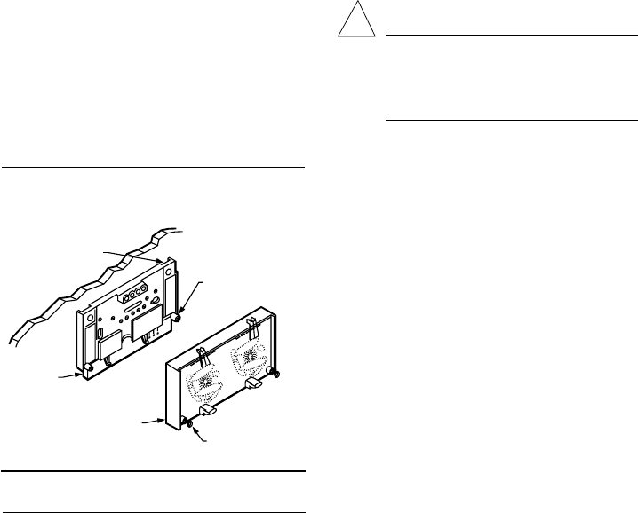
1. Remove the thermostat cover by pulling the bot-
tom edge of the cover away from the base until it snaps
free of the retaining posts.
NOTE: The cover is hinged at the top and must be
removed by pulling out at the bottom.
2. Carefully remove and discard the foam packing in-
sert that protects the mercury switches during shipment.
3. If thermostat is being used with a Q674 Subbase
that has LED indication, and the thermostat set point
scale does not have preprinted designations (EM.HT.,
CHECK, etc.), install the desired preprinted insert
packed with the subbase. Push both thermostat set
point levers to the far ends of the thermostat. Use index
finger to gently pull out the set point scale a fraction of
an inch. Insert the desired preprinted insert into the
recessed area behind the set point scale. Make sure
insert is completely seated in recessed area and reposi-
tion set point levers to the desired positions.
4. Turn over the thermostat base and note the spring
fingers that engage the subbase contacts. Make sure the
spring fingers are not bent flat, preventing proper elec-
trical contact with the subbase.
5. Set any adjustable heat anticipator indicators to
the respective current setting of each stage. See Setting
the Heat Anticipator section.
6. Note the tabs along the top inside edge of the
thermostat base. The tabs fit into the subbase notches.
Mount the thermostat base on the subbase and tighten
the captive mounting screws. See Fig. 12.
7. Place the upper edge of the thermostat cover on
the thermostat base and swing the cover downward until
it engages with the retaining posts on the base.
Fig. 12—Mounting thermostat on subbase.
THERMOSTAT
MOUNTING POST (2)
M936
50 60 70 80
50 60 70 80
HEAT
COOL
THERMOSTAT
MOUNTING SLOTS (2)
SUBBASE
THERMOSTAT
CAPTIVE MOUNTING
SCREWS (2)
Setting
SETTING THE HEAT ANTICIPATOR
On models with adjustable anticipation, set each ad-
justable anticipator to match the primary control current
draw. If the primary control nameplate has no rating or if
further adjustment is necessary, use the following proce-
dure to determine the current draw for each stage.
The current draw must be measured with the thermo-
stat removed and the power on.
Do not short across primary control terminals. This
may burn out the heat anticipator.
1. Connect an ac ammeter of appropriate range be-
tween the heating terminals of the subbase as follows:
• Stage 1: between W1 and RH or R.
• Stage 2: between W2 and RH or R.
2. Move the system switch to HEAT or AUTO, and
set the temperature to call for heat.
3. After one minute, read the ammeter and record
the reading.
4. After mounting the thermostat, set the adjustable
heat anticipator to match the readings measured in step 3.
TEMPERATURE SETTING
Move the heating and the cooling levers to the desired
positions. The minimum differential between heating and
cooling set points is 4° or 6° F [2° or 3° C], depending
on model; the setting levers are designed so they
cannot be set closer together than 4° or 6° F [2° or 3°
C], depending on the model.
SUBBASE SETTING
CAUTION
The Q647F1410 will run the EM. HT. relay
constantly when the system is in the EM. HT.
position. A cycling stat or limit must be pro-
vided external to the T874 to control the EM.
HT. relay.
System switching positions control thermostat op-
eration as follows:
OFF: Both the heating and cooling systems are off.
HEAT: Heating system is controlled by the thermo-
stat. Cooling system is off.
COOL: The cooling system is controlled by the
thermostat. Heating system is off.
EM.HT.: Emergency heat relay is energized. The cool-
ing system is off. When the heat pump is inoperable,
switch to EM. HT. setting. The Q674F1410 Subbase
will run EM. HT. relay continuously until the switch
position is changed. All other subbases will cycle
the EM. HT. relay according to room temperature
via the T874 mercury switch.
AUTO: Thermostat automatically changes between heat
and cool modes, depending on the indoor temperature.
Fan switching positions control fan operation as follows:
ON: Fan operates continuously.
AUTO: Fan operates with heating or cooling equip-
ment as controlled by the thermostat.
To switch positions, use thumb or index finger to
slide the lever to the desired position. Switch lever must
stop in detent over the desired function indicator mark
for proper circuit operation.
