


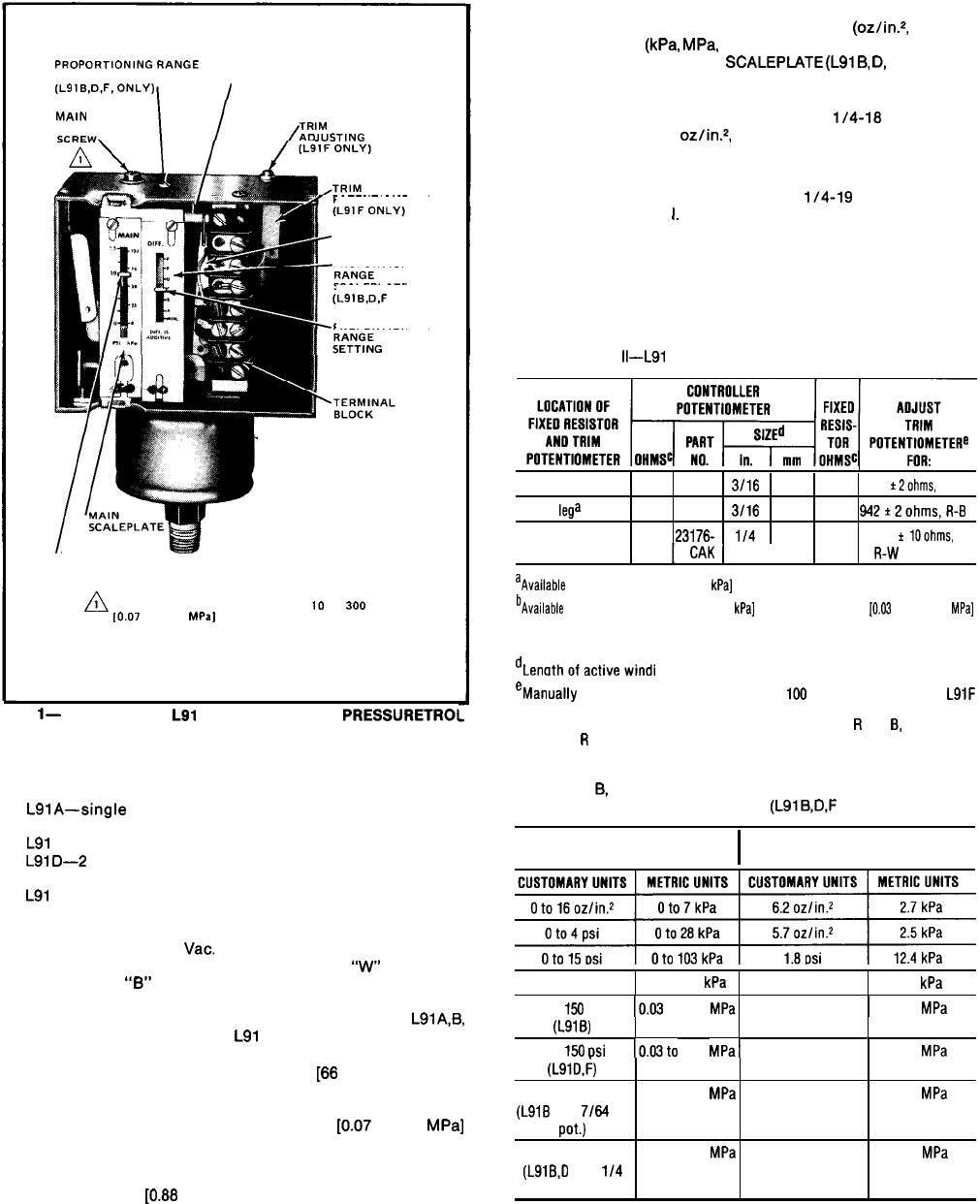
PROPcJRTlONlNG
RANGE
ADJUSTING SCREW
(L91B.D.F.ONLY)
CONTROLLER
POTENTIOMETER(S)
MAIN
SCALE
ADJUSTING
IM POTENTIOMETER
JUSTING
SCREW
POTENTIOMETER
WIPER ARM(S)
PROPORTIONING
SCALEPLATE
(L91B,D,F
ONLY)
PROPORTIONING
INDICATOR
(L91B.D.F ONLY)
-BELLOWS HOUSING
I
MAIN SCALE
SETTING
INDICATOR
n
1
KNURLED ADJUSTMENT KNOB ON IO TO
300
PSI
[0.07
TO 2.07
MPa,
MODELS.
El275
FIG.
l-
SETTING AN
L91
PROPORTIONING
PRESSURETROI
CONTROLLER.
MODELS:
LSlA-single
potentiometer; nonadjustable proportioning
range.
L91
B-single potentiometer; adjustable proportioning range.
L91D-2
potentiometers allow unison control of 2 motors;
adjustable proportioning range.
L91
F-single potentiometer; adjustable proportioning range;
fixed resistor and manually-adjustable trim potentiometer in
series with controller potentiometer.
ELECTRICAL RATING: 24
Vat.
POTENTIOMETER ACTION: Wiper moves toward
“w”
on pressure
rise; toward
“6”
on pressure fall. Potentiometer is field
replaceable.
POTENTIOMETER RESISTANCE: 140 ohms (nominal) for
LSlA,B,
and D models; see Table II for
L91
F models.
PRESSURE SENSING ELEMENT: Phos-bronze bellows.
MAXIMUM AMBIENT TEMPERATURE: 150 F [66 C].
MINIMUM AMBIENT TEMPERATURE: 32 F [0 C].
ADJUSTMENT MEANS: Screws on top of controller case; knurled
knob for main scale setting on 10 to 300 psi
[0.07
to 2.07 MPa]
models.
SET POINT: At low pressure end of proportioning
(throttling) range.
WEIGHT: 116.15 oz. [0.88 kg].
FINISH: Gray.
MAIN SCALEPLATE: Marked in both customary (oz/in.*, psi, or in.
Hg) and Metric
(kPa.
MPa.
or mm Hg) units.
PROPORTIONING RANGE SCALEPlATE
(L919,
D,
and F only):
graduated from A to F with a MIN (minimum) value below A. (See
Table Ill for the value of each division.)
MOUNTING MEANS: Fitting on bellows has
l/4-18
NPT threads
(external on 0 to 16
oz/in2,
0 to 4 psi, and 0 to 15 psi models;
internal on all other models) for mounting on a pipe or steam trap
(siphon loop).
NOTE: Some models are available with
l/4-19
BSP-TR internal
threads: see Table
I.
Also can be surface mounted by screws through 2 holes
(knockouts) in back of case.
TABLE
II-L91
F RESISTANCE VALUES AVAILABLE
In
Blega
11.2
23367F 3/16
4.8
470
518
t2ohms,
R-B
In
B
lega
17.6
233676 3/16
4.8
870
942+2ohms,R-B
ln
w
legb 380.0
23176- l/4
6.4
2080
2515
f
lOohms,
aAvailable
for Oto 15 psi
[Ot o
103
kPa]
models only.
bAvailable
for Oto 15 psi IOto 103
kPa]
and 5to 150 psi
[0.03
to 1.03
MPa]
models.
'Nominal resistancevalues.
eManually
adjustable trim potentiometer is
100
ohms (nominal)
in all
L91F
models. With zero pressure on the bellows, adjust the trim potentiometer to
obtain the resistance values listed between terminals
R
and
8,
or between
terminals
R
and W, as indicated.
TABLE III-APPROXIMATE VALUE OF EACH DIVISION
(A TO
9,
B TO C. etc.) ON PROPORTIONING (Throttling)
RANGE SCALEPLATE
(L919,D.F
only)
OPERATING
RANGE
I
VALUE OF EACH
DIVISION
CUSTOMARY UNITS METRIC UNITS CUSTOMARY UNITS METRIC UNITS
~
2 to
50 psi
14
to
345
kPa 4.7psi
32.4
kPa
5 to 156
psi
10.03to
1.03 MPal
7.8psi
1
0.054
MPa
(L91B)
5to
150
osi
10.03to
1.03
(LSlD,i)
MPal
6.7
psi
1
0.046
MPa
10
to
300
psi
0.07
to
2.07 MPa
16.4psi
0.113 MPa
(L918
with 7/64 in.
pot.)
10to
300
psi
0.07
to
2.07 MPa
13.8psi
0.095 MPa
(LSlB,D
with
l/4
in. pot.)
PRINTED IN U.S.A.