


60-2553—3 4
L8151A
INSTALLATION
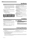
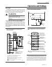
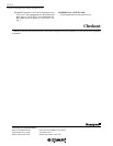
Fig. 3—Remote bulb installation.
All wiring must comply with local electrical codes and
ordinances. The limits given in the Specifications section
must not be exceeded when applying this control. Use
manufacturer instructions when wiring controlled equip-
ment or refer to typical hookups in Fig. 4 through 6.
When the B1 terminal on the device being replaced is
1/4 in. tab terminal, use the existing wiring harness termi-
nals to install the replacement device. When the B1 termi-
nal on the device being replaced is a screw terminal, insert
the provided tab terminal to screw terminal adapter on the
1/4 in. tab terminal of the replacment device. After the
adapter is installed, the existing wraparound wire end can
be reused to make an electrical connection to the B1 termi-
nal.
NOTE: Do not use a push type ratchet screwdriver.
1. Strip 7/16 in. of insulation from the wire end.
2. Wrap the wire at least three-fourths of the distance
around the screw as shown.
3. Using a standard, flat-headed screwdriver, tighten the
screw until the wire is snugly in contact with the screw and
contact plate.
4. Tighten the screw an additional one-half turn.
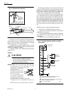
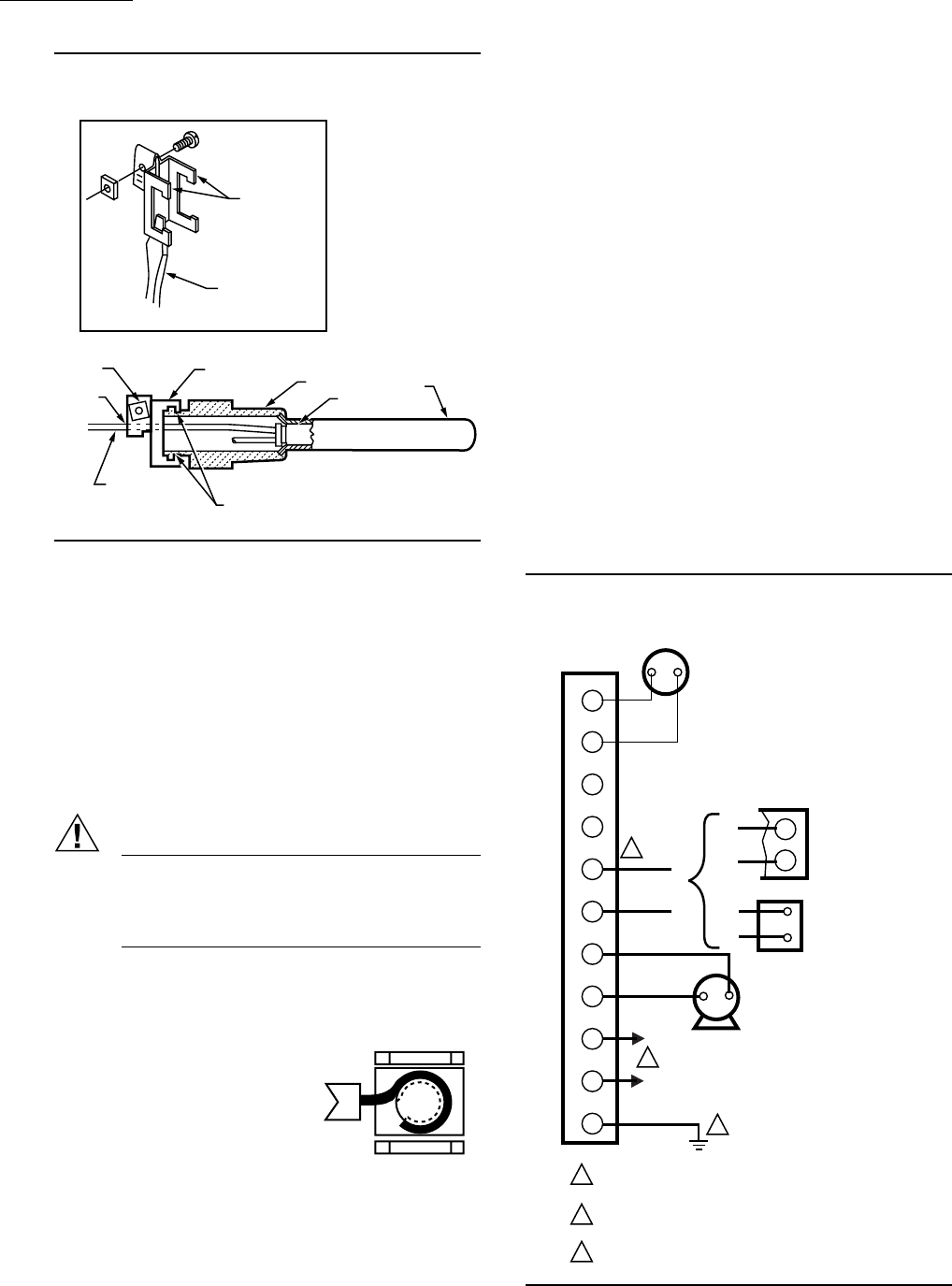
Fig. 4—Typical hookup for L8151A in a single
zone system.
M8777
WELL
BULB
SPUD
MOUNTING
CLAMP
A
DRAW
NUT
TUBING
B
INSERT— MOUNTING CLAMP
SCREWDRIVER
SPREAD JAWS
TO FIT OVER
RIDGE ON SPUD
OF WELL
JAWS
4. With part no.121371AA Retainer Clamp attached to
well spud (be sure jaws of clamp hook over ridge at end of
spud, as shown at points A), adjust tubing to fit through
retainer clamp groove, as shown at point B.
5. Tighten draw nut so that retainer clamp is firmly
attached to well spud and tubing is held securely in place. Be
careful not to damage the capillary.
6. Carefully coil the excess capillary at the bottom of the
Aquastat
®
case.
WIRING
CAUTION
• Disconnect power supply before wiring to avoid
electrical shock or equipment damage.
• Be sure the terminal connections are inside an
enclosure that meets local codes.
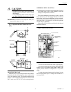
IMPORTANT: Terminals on the L8151A Aquastat
®
Relay
are approved for use only with copper wire. The
terminals allow wraparound wiring only.
1. Strip 7/16 in. of insulation
from the wire end.
2. Wrap the wire at least three
fourths of the distance around
the screws as shown.
3. Use a standard flat-headed
screwdriver to tighten the
screw until the wire is snugly
in contact with the screw and contact plate.
4. Tighten the screw an additional one-half turn.
NOTE: Do not use a push-type ratchet screwdriver.
M8843
L1
(HOT)
L2
1
2
3
1
2
3
POWER SUPPLY. PROVIDE DISCONNECT MEANS AND
OVERLOAD PROTECTION AS REQUIRED.
CONTROL CASE MUST BE CONNECTED TO EARTH GROUND.
USE GROUNDING SCREW PROVIDED.
B1 IS 1/4 IN. TAB TERMINAL.
M8886
T
T
ZC
ZR
B1
B2
C1
C2
1
2
G
THERM.
BURNER
LINE
2
1
CIRC.
LOW VOLTAGE
THERMOSTAT
LINE VOLTAGE
CIRCULATOR
X
X
X
X
X
X
OR
OIL BURNER
RELAY
LINE TERMINAL
LINE VOLTAGE
GAS VALVE