


3 68-0063—3
L8104A,B,C,D
SPECIFICATIONS
DIMENSIONS:
L8104: Fig. 1.
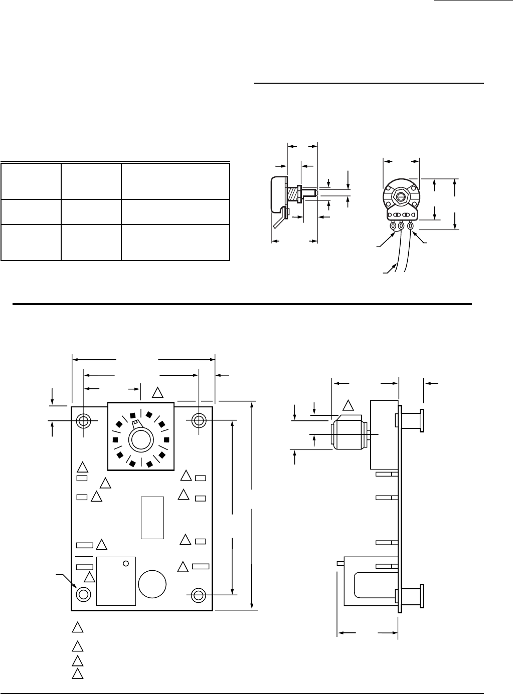
L8104A,B: Fig. 2.
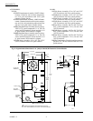
L8104C,D: Fig. 3.
APPROVALS:
Underwriters Laboratories Inc. Component Recognized:
File No. MP466, Guide No. MBPR2.
American Gas Association Certified: Report No. 70-22A.
Canadian Gas Association Certified: Report No. 1029-
CC/T-6849.
OTHER SYSTEM COMPONENTS (Order separately):
available through your Honeywell sales representative.
Please provide the ordering information indicated in the
Ordering Information section to assure correct replace-
ment components.
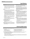
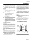
Fig. 1—Approximate dimensions in in. (mm) of
L8104 Remote Potentiometer and Sensing Bulb.
FACTORY
INSTALLED
JUMPER
12 IN. (305 MM)
LEADWIRES
TERMINALS
1, 2 & 3
3
1
2
REMOTE MOUNT POTENTIOMETER
M413
3/4
(19)
3/8
(10)
3/8
(10)
5/32
(4)
3/8 DIA.
(10)
1-1/4 (32)
15/16
(24)
1-1/16
(27)
1-3/8
(35)
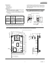
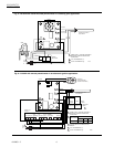
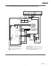
Fig. 2—Approximate dimensions in in. (mm) of L8104A,B Electronic Control Module.
REPLACEMENT PARTS: Replacement electronic control
modules, sensing bulbs, and remote potentiometers are
140
120
160
180
100
SEN-1
SEN-2
LOWER
UPPER
24 V
HOT
ONLY
COM.
RELAY
NO
3/8
(10)
1/2
(13)
1-1/8 (29) 9/32
(7)
1 (25)
3-15/32
(88)
2-15/16
(75)
.170 DIA.
(FOUR)
1/4
(6)
(TWO)
1/4
(6)
(TWO)
3/4 (19)
1-15/16 (49)
2-15/32 (63)
1
1
4
4
4
4
3
3
3
4
2
1
2
3
4
L8104A,B ELECTRONIC CONTROL MODULE
MODELS WITH REMOTE POTENTIOMETER HAVE TWO 1/4 IN.
TAB TERMINALS IN PLACE OF THE POTENTIOMETER.
L8104A DOES NOT HAVE UPPER OR SEN-2 TERMINALS.
1/4 IN. TAB TERMINALS (3)
3/16 IN. TAB TERMINALS (5)
M113C
System
Electronic
Ignition
Module Gas Control
Standing
pilot
— VR800, VR8200, or any
rated 2.0A or less
Intermittent
pilot
S86F,H;
S8600H;
S8610F,H
VR8440, VR8204 or
any rated 2.0A or less