


L4006A,B,E,H AQUASTAT® CONTROLLERS
60-0915—5 2
1. Remove the old control.
2. Refer to the cover insert of the old control to identify
and tag each lead as it is disconnected.
3. Leave the old well in place if it is suitable.
If Well is Otherwise Suitable But Does Not Fit The
L4006 Immersion Well Clamp
Use a 124904 Well Adapter (order separately, see form
68-0040) to secure the L4006 to the old well. The adapter
has a flange at one end for fastening the L4066 adapter
clamp.
1. Loosen, but do not remove, the two adapter clamp
screws (see Fig. 1).
2. Slide the adapter onto the capillary and short tube;
see Fig. 2 inset.
3. Make sure the flanged end of the adapter fits into
the hole in the case. Position the adapter well clamp
snugly over the flange on the adapter, then tighten
the clamp screws.
4. Insert the bulb into the well, as shown in Fig. 2. If
necessary, use the heat-conductive compound as
instructed in the IMPORTANT statement on page 1.
5. Tighten the setscrew (if one is present in the old
well spud) against the adapter.
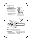
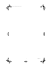
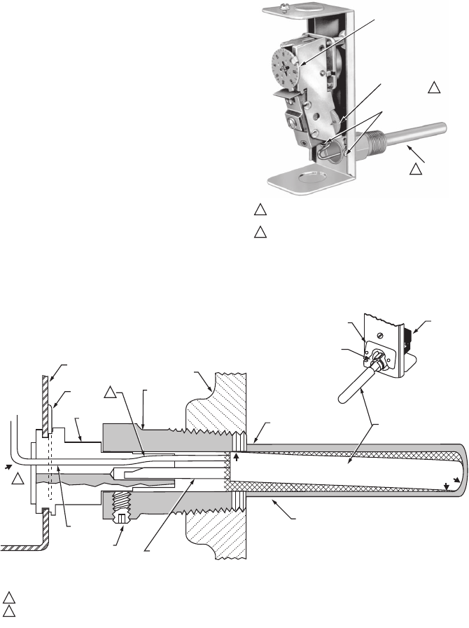
Fig. 1. Internal view of L4006A,B with horizontal well.
L4006E is the same with reset button added.
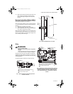
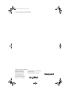
Fig. 2. Bulb in immersion well and use of adapter.
If the Old Well Is Unsuitable.
1. Drain the system and remove the well.
2. Select a new well from form 68-0040 (order well
separately).
3. Install the new well, refill the system and check for
leaks.
4. Loosen, but do not remove, the two adapter clamp
screws (Fig. 1).
5. Insert the sensing bulb into the well until it bottoms
as show in Fig. 2. Add heat-conductive compound,
if necessary, as instructed in the IMPORTANT
statement on page 1.
M4679
SETPOINT
INDICATING DIAL
DIFFERENTIAL
ADJUSTMENT
WHEEL
ADAPTER CLAMP
SCREWS
IMMERSION
WELL
MODELS WITH FIXED DIFFERENBTIALS DO NOT INCLUDE
ADJUSTING WHEEL.
VERTICALLY MOUNTED IMMERSION WELL IS ATTACHED
TO THE BOTTOM OF THE CASE.
1
2
1
2
CONTROLLER
CASE
ADAPTER
ADAPTER
CLAMP
IMMERSION
WELL SPUD
BOILER
OLD IMMERSION
WELL ASSEMBLY
BACK OF
CASE
ADAPTER
ADAPTER
CLAMP
SENSING
BULB
HEAT-CONDUCTIVE COMPOUND
SETSCREW
CAPILLARY
TUBE
(C)
SHORT TUBE
FITS IN CENTRAL
RECESS OF
ADAPTER
SLIGHTLY BEND IN TUBES SHOULD HOLD BULB IN GOOD THERMAL CONTACT WITH THE WELL AT TWO OPPOSITE POINTS, AS IN (A) AND (B).
ASSURE THAT TUBES FIT FREELY IN ADAPTER SO THAT TENSION OF THE CAPILLARY TUBE AT POINT (C)
HOLDS THE SENSING BULB IN GOOD THERMAL CONTACT WITH THE BOTTOM OF WELL AT POINT (D).
M4678
1
2
2
(D)
(B)
(A)
1
60-0915-5.fm Page 2 Wednesday, June 20, 2007 9:16 AM