


HE225A,B AND HE265A,B BYPASS FLOW-THROUGH HUMIDIFIER
68-0244
4
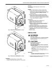
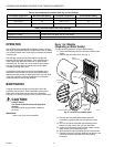
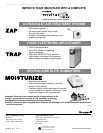
Fig. 3. Typical humidifier installation locations.
IMPORTANT
Mount the humidifier at least 3 in. (76 mm) above
the furnace jacket to allow adequate space for the
solenoid valve and drain line. Check that there is
adequate space above the humidifier to remove and
install the humidifier cover.
2. Tape the template in position and trace around the
template.
3. Remove the template and carefully cut the rectangular
opening.
4. Disassemble the humidifier; remove the cover and take
out the humidifier pad assembly. See Fig. 4.
NOTE: Sidewalls are interchangeable for either left or
right by-pass installation. To change direction,
remove the screws holding each sidewall,
switch sidewall locations and reinstall the
screws.
5. Position the humidifier housing in the opening (be sure
it is level), so the locking tabs are in place on the lower
sheet metal edge of the opening.
6. Secure the humidifier housing to the opening at the top
and bottom using sheet metal screws.
7. Locate the other plenum and cut an opening for a 6 in.
(152 mm) collar.
8. Install the 6 in. (152 mm) collar.
NOTE: Be sure to install a duct damper for summer
shutoff on systems with air conditioning.
9. Install a 6 in. (152 mm) diameter duct from the collar to
the humidifier.
NOTE: Some installations require a 90° elbow
attachment to the collar.
10. Seal the duct connections with duct tape.
NOTE: To avoid sagging and stress on the humidifier,
add support when ducting is longer than
4 ft (120 cm).
11. Reinstall the humidifier pad assembly in the humidifier
housing.
NOTE: Be sure the water feed tube is not pinched or
kinked.
12. Hinge the cover in place and secure with the
thumbscrew located at the bottom of the cover.
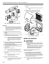
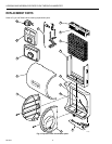
Fig. 4. Humidifier components.
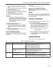
WIRING THE HUMIDIFIER
CAUTION
Hazardous Voltage.
Can cause personal injury or equipment damage.
• Disconnect the power supply before installing or
servicing.
• On multispeed blower applications, do not wire the
high voltage side of the transformer to the same
power source that services the furnace blower.
Premature transformer burnout may occur.
All wiring must comply with applicable local codes,
ordinances and regulations.
1. Mount the transformer in a convenient location.
2. Connect wires to the 120V side of the transformer.
3. Wire the humidifier solenoid valve, current sensing
relay, or sail switch, humidity control and transformer.
Refer to the humidity control installation instructions for
mounting and wiring information.
NOTE: Select models of fan centers include humidifier taps
so the current sensing relay or sail switch is not
needed.
M12248C
HORIZONTAL
DOWN
FLO
LOWBOY
HIGHBOY
M14672
WATER
FEED NOZZLE
FRAME
HUMIDIFIER
HOUSING
WATER
FEED TUBE
HUMIDIFIER
PAD ASSEMBLY
COVER
SIDEWALL
BY-PASS SIDEWALL