


H8908B HUMIDISTAT H8908C DEHUMIDISTAT
3 69-1341
WIRING
CAUTION
Personal Injury Hazard.
Power supply can cause electrical shock and
injury.
Disconnect power supply before installation or
servicing.
All wiring must comply with applicable local codes, ordi-
nances and regulations. Make wiring connections
according to humidifier (or dehumidifier/ventilator)
instructions, if available; otherwise, see typical wiring
diagrams in Fig. 5 through 12.
IMPORTANT
Select models of fan centers include humidifer
taps so the current sensing relay or sail switch
is not needed.
If not using a current sensing relay or sail
switch, the humidifier must be energized dur-
ing blower motor cycles for proper operation.
On multispeed blower applications, do not wire
the high voltage side of the transformer to the
same power source that services the furnace
blower. Premature transformer burnout can
occur.
On HE360 fan powered humidifier models,
only the two yellow wires are connected to the
control. The remaining two red wires are only
used with electronic humidity controls.
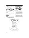
Fig. 5. Typical wiring diagram for
system with fan interlock.
Fig. 6. Typical wiring diagram for system
with 2-speed fan motor.
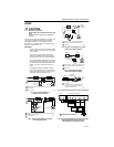
Fig. 7. Typical wiring diagram of current
sensing relay with humidifier.
Fig. 8. Typical wiring diagram
of sail switch with humidifier.
Fig. 9. Typical wiring diagram for steam humidifiers.
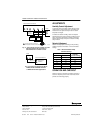
Fig. 10. Typical parallel wiring of humidity controller
with Chronotherm® IV Thermostat for
dehumidification and mildew control.
1
1
2
PROVIDE DISCONNECT MEANS AND OVERLOAD PROTECTION
AS REQUIRED.
24 VAC WIRING.
2
HUMIDIFIER
TRANSFORMER
FURNACE
FAN
MOTOR
H8908B
FAN CONTROL
L1
(HOT)
L2
M13368
POWER
SUPPLY
1
1
HL
C
2
POWER SUPPLY. PROVIDE DISCONNECT MEANS AND OVERLOAD
PROTECTION AS REQUIRED.
24 VAC WIRING.
2
HUMIDIFIER
TRANSFORMER
2-SPEED
FAN
MOTOR
DPST
SWITCHING
RELAY
H8908BFAN CONTROL
L1
(HOT)
L2
M13384
POWER
SUPPLY
M13386
L1
(HOT)
L2
1
2
1
2
POWER SUPPLY. PROVIDE DISCONNECT MEANS
AND OVERLOAD PROTECTION AS REQUIRED.
24V WIRING.
HUMIDIFIER
TRANSFORMER
WATER
SOLENOID
LEAD WIRE
CURRENT
SENSING
RELAY
C
LO
HI
H8908B
M13385
L1
(HOT)
L2
1
2
1
2
POWER SUPPLY. PROVIDE DISCONNECT MEANS
AND OVERLOAD PROTECTION AS REQUIRED.
24V WIRING.
HUMIDIFIER
TRANSFORMER
H8908B
SAIL
SWITCH
M13387
1
1
1
FOLLOW THE INSTALLATION INSTRUCTIONS
INCLUDED WITH THE STEAM HUMIDIFIER
TO WIRE THE SYSTEM FAN.
NOTE:
HUMIDIFIER
H8908B
TO
SYSTEM
FAN
HUMIDISTAT
TERMINALS
FAN WIRING
TERMINALS
24V WIRING.
B
O
WY
G
R
HEATING
RELAY OR
VALVE COIL
COOLING
CONTACTOR
COIL
FAN
RELAY
COIL
CHRONOTHERM
®
IV THERMOSTAT
PROVIDE OVERLOAD PROTECTION AND
DISCONNECT MEANS AS REQUIRED.
M13366
H8908C
1
1