


H7625B; H7635B,C; H7655B DUCT-MOUNT AND OUTDOOR-MOUNT HUMIDITY/TEMPERATURE SENSORS
63-2579—3 6
APPENDIX
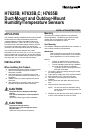
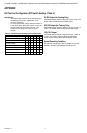
RH Test and Configuration DIP Switch Settings (Table 3)
IMPORTANT
• Only adjust these switches for troubleshooting or
recalibrating the sensor. (Adjustment is not
normally necessary.)
• For normal operation, always keep DIP switch 3
in the ON position. When DIP switch 3 is off, the
RH transmitter cannot read the sensor. This
inability-to-read forces the output to never
change.
Table 3. Test/Calibration Settings (Six-Switch Block).
0% RH Output (for Testing Only)
Transmitter always outputs a signal of 4 mA or 0 Vdc. The
sensor does not affect the transmitter output.
50% RH Output (for Testing Only)
Transmitter always outputs a signal of 12 mA, 2.5 VDC, or
5 VDC. The sensor does not affect transmitter output.
100% RH Output
Transmitter always outputs a signal of 20 mA, 5 VDC, or
10 VDC. The sensor does not affect the transmitter
output. Sensor doesn’t affect the transmitter output.
Normal Operating Condition
DIP switch 3 must be set in the On position for normal
operation. All other DIP switches must be set Off.
Setting 654321
Normal Operation (Default) — — — On — —
0% RH Output On—————
50% RH Output —On————
100% RH Output — — On — — —
Increment RH Output — — — — On —
Decrement RH Output —————On
Reset to Original Calibration — — — — On On