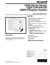
F500 WHOLE HOUSE/ LIGHT COMMERCIAL HEPA FILTRATION SYSTEM
68-0263-2 4
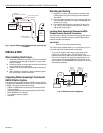
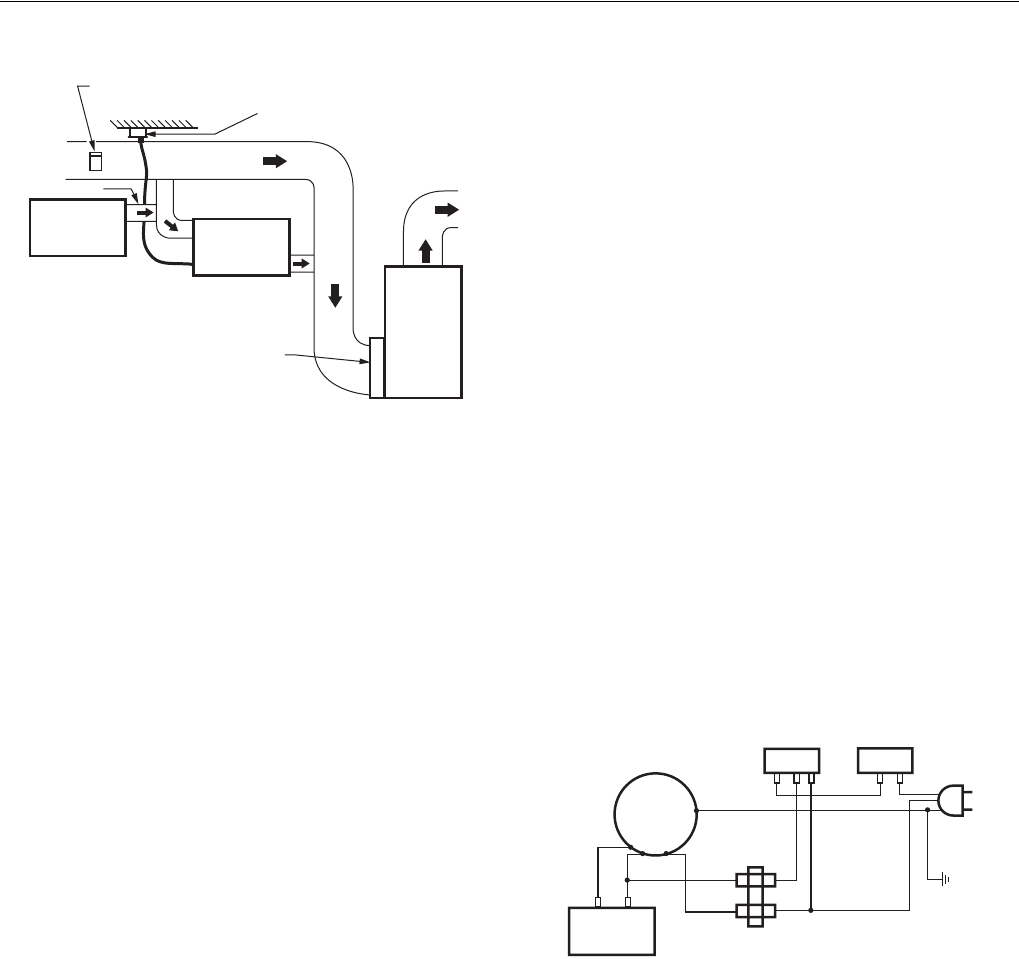
Fig. 4. Typical F500 bypass installation with heat recovery
ventilator.
INSTALLATION
When Installing this Product…
1. Read these instructions carefully. Failure to follow these
instructions could damage the product or cause a haz-
ardous condition.
2. Check the ratings on the product to make sure the prod-
uct is suitable for your application.
3. Installer must be a trained, experienced service techni-
cian.
4. After installation is complete, check out product opera-
tion as provided in these instructions.
Unpacking Whole House/Light Commercial
HEPA Filtration System
The Whole House/Light Commercial HEPA Filtration System
is shipped fully assembled. Check that all the components are
included. The carton contains the following:
• F500A or F500B Whole House/Light Commercial HEPA
Filtration System.
• Activated carbon-odor filter, pleated prefilter, HEPA filter.
• HEPA AIRWATCH™ Indicator.
• Four isolation mounting straps.
• Literature.
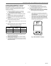
Mounting and Ducting
1. Mount four vibration isolation straps to the side of the
HEPA System using the mounting screws located on
the cabinet.
2. Securely fasten the other ends of the straps to the floor
joists with wide-head nails or screws (not supplied); be
sure the unit is level.
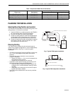
3. Connect the HEPA System to the return air duct. See
Fig. 1 and 2. Seal all duct joints with caulk, mastic, or
high quality foil duct tape.
Installing Whole House/Light Commercial HEPA
Filtration System Electrical Connections
The F500 has a 3-prong, 120 Vac connector plug with ground.
If further wiring is required, contact a qualified electrician to
make all electrical connections.
IMPORTANT
Be sure the unit is grounded correctly.
The F500 can be installed either to run continuously or to run
only when the HVAC system blower is operating.
• To run the air cleaner continuously, simply plug the air
cleaner into a 120 Vac outlet. The unit turns on and
operates continuously when the power switch is turned on.
• To run the air cleaner only when the system blower is on,
use an optional Honeywell S688A1007 Sail Switch in the
return air duct. See the S688A product literature for correct
installation procedures.
Fig. 5. F500 internal wiring diagram.
S688A1007
SAIL SWITCH (OPTIONAL)
120 VAC 60 HZ SUPPLY
WITH GROUND
RETURN AIR
FRESH AIR
HEAT
RECOVERY
VENTILATOR
F500
HIGH EFFICIENCY
AIR CLEANER
M20264
A
AIR
HANDLER
(FURNACE
)
ON/OFF
SWITCH
DOOR
INTERLOCK
BLACK
GREEN
WHITE
M20265
TERMINAL
BLOCK
CAPACITOR
FAN
MOTOR
POWE
R
CORD
BROWN
BROWN
WHITE
BLACK
BLUE


