


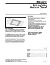
F118 IN-CEILING MEDIA AIR CLEANER
68-0209-2 Revised 11-07 6
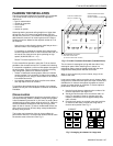
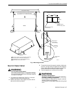
5. Standing on a secure platform, lift the cabinet body and
insert it into the frame in the drop ceiling.
6. Attach the free end of the wire to the structural ceiling.
Align the cabinet edge with the upper side of the T-bars,
without releasing the full weight onto the T-bars.
7. Verify that the wire is strong enough to bear the load of
the F118 before completing installation.
8. Level the air cleaner.
Electrical Hookup
All wiring must comply with applicable codes and ordinances.
The air cleaners are internally pre-wired.
IMPORTANT
Check that the air cleaner is grounded for proper
operation and safety.
Canadian Installations: Do not install in ceilings
with thermal insulation value greater than R-40.
If installing an additional wall switch to regulate the air cleaner
speed, only the Honeywell 32000234 (41105) Variable Speed
Switch (optional) is recommended. Using a different speed
controller can void the warranty.
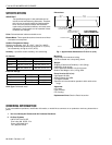
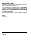
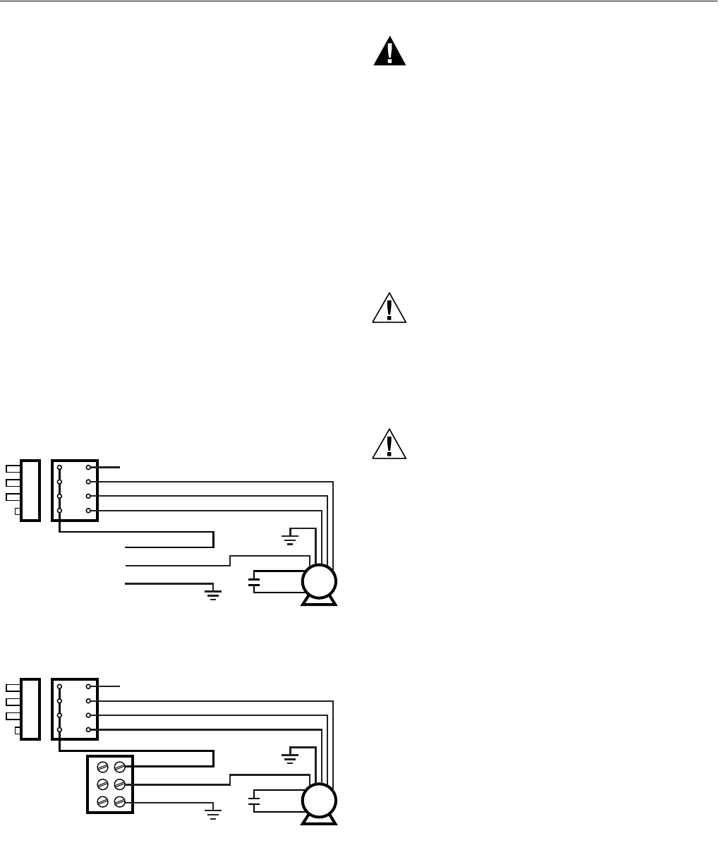
1. Pull the wire to the electrical box through the hole in the
top of the cabinet. Refer to Fig. 5 and 6 for typical wiring
diagrams.
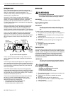
Fig. 5. Typical F118 120V, 60 Hz Wiring Diagram.
Fig. 6. Typical F118 230V, 50 Hz Wiring Diagram.
WARNING
Fire or Electric Shock Hazard.
Can cause personal injury or equipment damage.
Be careful performing electrical check when air
cleaner is turned on.
Be careful when working near air cleaner moving
parts.
2. Turn on air cleaner power and check for proper opera-
tion for two to three minutes. There should be a smooth,
powerful blower sound with air discharging from both
ends of the air cleaner.
3. Turn off the power.
Install Filters
CAUTION
Eye Exposure.
Harmful dust can obstruct or injure unshielded
eyes.
CPZ module normally releases dust when handled.
Always wear safety glasses when installing or remov-
ing CPZ module.
CAUTION
Filter Media Damage Hazard.
Damage to the filter media can easily occur.
Do not touch the pleated filter media.
Handle only the filter frame.
1. Install the particle filter and pre-filter that is wrapped
around the particle filter:
a. Push aside the support rods.
b. With both hands, slide the filter up into the central
portion of the cabinet and hold it in place.
c. Pull the support rods down and toward the center,
until the filters are held in place and the weight com-
pletely supported.
IMPORTANT
Avoid excessive pressure on individual adsorbent
panels.
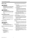
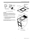
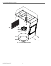
1. Install the CPZ sorbent modules:
a. Remove CPZ™ sorbent modules from the packag-
ing.
b. See Fig. 7 to install CPZ module at each end of the
cabinet. Tilt and then push the module up about ten
inches into the opening. Then allow it to rotate down
so the bottom rests on the inside cabinet ledge.
ON
HI
MED
LO
1
2
3
4
BLACK
BLUE
RED
GREEN
ORANGE
YELLOW
BLACK
WHITE
GROUND GREEN
INPUT:
HIGH SPEED 2.8A AT 120V - 60 HZ
MED SPEED 2.0A AT 120V - 60 HZ
LOW SPEED 1.4A AT 120V - 60 HZ
FAN MOTOR
M16210A
ON
HI
MED
LO
1
2
3
4
BLACK
BLUE
RED
GREEN
ORANGE
YELLOW
BROWN
BLUE
GREEN/YELLOW
INPUT:
HIGH SPEED 2.8A AT 230V - 50 HZ
MED SPEED 2.0A AT 230V - 50 HZ
LOW SPEED 1.4A AT 230V - 50 HZ
FAN MOTOR
M14417