


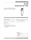

EA79
INSTALLATION
VI’I-IEN INSTALLING THIS PRODUCT...
1. Read these inslructions carefully. Failure to follow
them could dama~ the rxoduct or cause a hazardous
- .
c0ndi1i0n.
2. Check the radngs given in the instructions and on
the product LO make sure lhe product is suilable for your
application.
3. 1r1s~alle.r must be a uaiwd, experienced sew&x
technician.
4. Afrer installalion is complele, check ou( product
operation as provided in these instmctions.
Do nol use tools LO adjust Ihe EA79 or damage
to vent may resuh Use hands only to ad.;usi
venl. A wrench may be used only on hex during
mstallation.
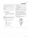
LOCATION
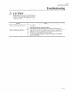
Install Ihe EA79 on the positive side of the circulaloi-
pump at the poini when alr will accumulate. This is usuall)
Lhe high point of the supply or ihe return main in Ihe sysiem
as shown in Fig. 3.
Fig. 3--install EA79 at high point in system
INSTALLATION
I. Fit EA79 vent in piping at a location as specified in
the Localion section.
2. Turn EA79 until venl fits tightly on piping. USC a
wrench to securely tighien hex.
3. If safkly drain connection is desired, inswll a pipe
between vent discharge and drain using Q122AlOOl %I~?
waste Conmclor.
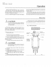
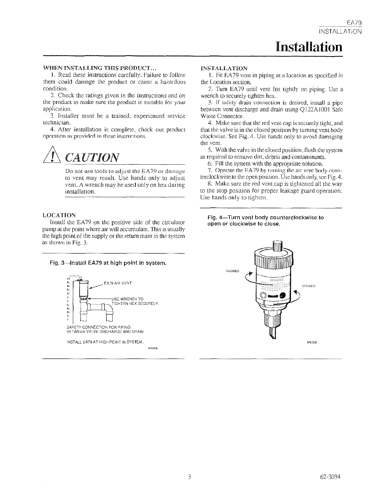
4. Make sure thal Lhc red vent cap is securely Light, and
thal the valve is in the closed position by luming vent body
clockwise. See Fig. 4. Use hands only to avoid damaging
the vmt.
5. Wiih lhe valvein theclosed position, flush the system
as required to remove din, debris and contaminanis.
6. Fill the system with the appropriate solution.
7. Operate he EA79 by turning the air vent body coun-
vxckxkwise to tie open position. Use hands only, see Fig. 4.
8. Make pure the red vent cap is Ughlened all lhe way
to the slop posilion for proper leakage guard operalion.
Use hands only to tighten.
Fig. 4-Turn vent body counterclockwise to
open or clockwise to close.
3 62.3034