


CT87A,B,J ROUND® THERMOSTAT
69-0274-6 4
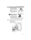
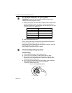
1. If using the cover ring: Position the cover ring against the wall so
that the arrow in the middle of the cover ring is pointing up.
2. Position the wallplate or subbase.
• If using cover ring: Place the wallplate/subbase over the cover
ring. Rotate the wallplate/subbase until the wiring openings are
aligned and the two screw holes on the left and right side of the
wallplate/subbase align with the screw holes on the cover ring.
You will be inserting screws through these holes into the wall.
• If attaching wallplate directly to the wall: Position so that the
UP indicator on the wallplate is on top.
• If attaching subbase directly to the wall: Position so that the
fan and heating/cooling switches are on the top.
3. Use a pencil to mark the center of the screw holes on the left and
right sides of the wallplate or subbase.
4. Remove the wallplate/subbase and cover ring, and drill two 1/16-in.
holes at the locations you marked.
5. Reposition the cover ring (if used) and wallplate/subbase over the
holes, pull the wires through the wiring opening, and loosely insert
the two 1-in. screws into the drilled holes.
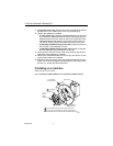
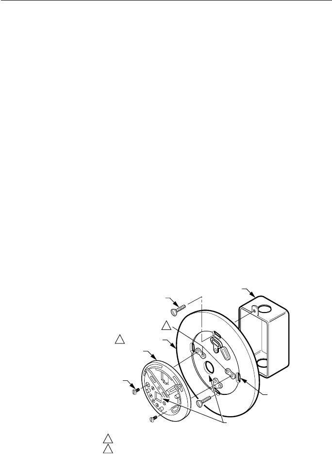
If installing on an outlet box
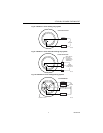
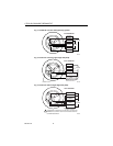
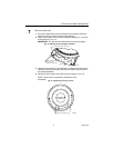
Refer to Fig. 5 as you work.
Fig. 5. Installing wallplate/subbase on an outlet box (subbase shown).
M2018
7
OUTLET BOX
SUBBASE
COVER RING
1
THERMOSTAT
WIRING HOLE
THE TWO INNER HOLES ARE USED WITH WALLPLATE.
2
IF OUTLET BOX IS HORIZONTAL, MOUNT COVER RING IN
POSITION SHOWN, BUT FASTEN WITH SCREWS THROUGH "A".
2
1
A
1/2 IN. BINDING
HEAD SCREW (2)
1
/4 IN.
R
OUND
H
EAD
S
CREW (2)