


CT3451 PROGRAMMABLE THERMOSTAT
3 69-1620—1
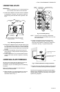
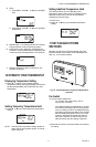
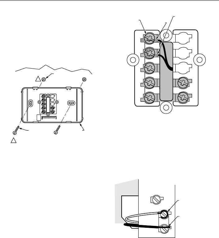
3 MOUNT WALLPLATE
IMPORTANT
Level for appearance only. The thermostat func-
tions normally even when not mounted level.
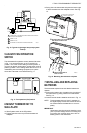
❑ Position the wallplate on the wall. Level the wallplate
for appearance, if desired. Use a pencil to mark the
two mounting holes that best fit the application. See
Fig. 3.
Fig. 3. Mounting wallplate to wall.
❑ Remove the wallplate from the wall and drill two 3/16-
in. holes in the wall (if drywall). For firmer wall material
such as plaster or wood, drill 7/32-in. holes. Gently tap
provided anchors into the drilled holes until flush with
the wall.
❑ Reposition the wallplate, pulling wires through the
wiring opening. Loosely insert the mounting screws
into the holes.
❑ Level for appearance only; the thermostat functions
correctly even when not level. Tighten the mounting
screws.
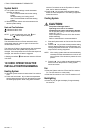
4 WIRE WALLPLATE TERMINALS
All wiring must comply with local electrical codes and
ordinances. If unsure about household wiring
procedures, call your local heating and air conditioning
contractor.
Refer to the labels you placed on wires when you
removed your old thermostat.
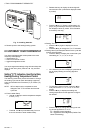
❑ Match the letter of your old thermostat wire with the
terminal of the corresponding letter on your new
thermostat. Refer to Fig. 4.
Fig. 4. Connecting wiring.
NOTE: To ensure correct mounting of thermostat,
restrict all wiring to the shaded area in the cen-
ter of the terminals.
❑ Loosen the terminal screws and slip each wire
beneath its matching terminal. The shape of the
terminals permit insertion of straight or wraparound
connections. See Fig. 5. Tighten the terminals.
Fig. 5. CT3451 methods for wiring connection.
❑ Plug the hole in the wall with insulation to help prevent
drafts from adversely affecting thermostat operation.
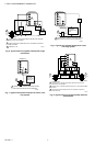
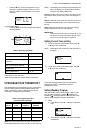
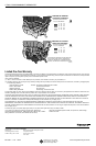
The CT3451 Thermostat is powered with 3AA alkaline
batteries and is adaptable to most 18 to 30 Vac heating-
cooling systems. Refer to Fig. 6 through 10 for typical
system wiring diagrams.
M12202A
WALL
WALL
ANCHORS (2)
WALLPLATE
WHEN USING WALL ANCHORS, DRILL 3/16 INCH
HOLES FOR DRYWALL, 7/32 INCH HOLES FOR
PLASTER OR WOOD.
MOUNTING
SCREWS (2)
1
1
T
ERMINAL
S
CREW
M12559A
G
R
Rc
Y
W
B
O
FOR STRAIGHT
INSERTION STRIP
5/16 IN. (8 MM)
FOR WRAPAROUND
STRIP 7/16 IN. (11 MM
)
M1253
7
FOR WRAPAROUND, STRIP
7/16 IN. (11 mm)
FOR STRAIGHT INSERTION
,
STRIP 5/16 IN. (8 mm)