


4
WIRE
AND
MOUW
.THERMOSTAT
wntinued)
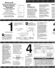
Recheck for level positioning, and firmly
tighten both mounting screws
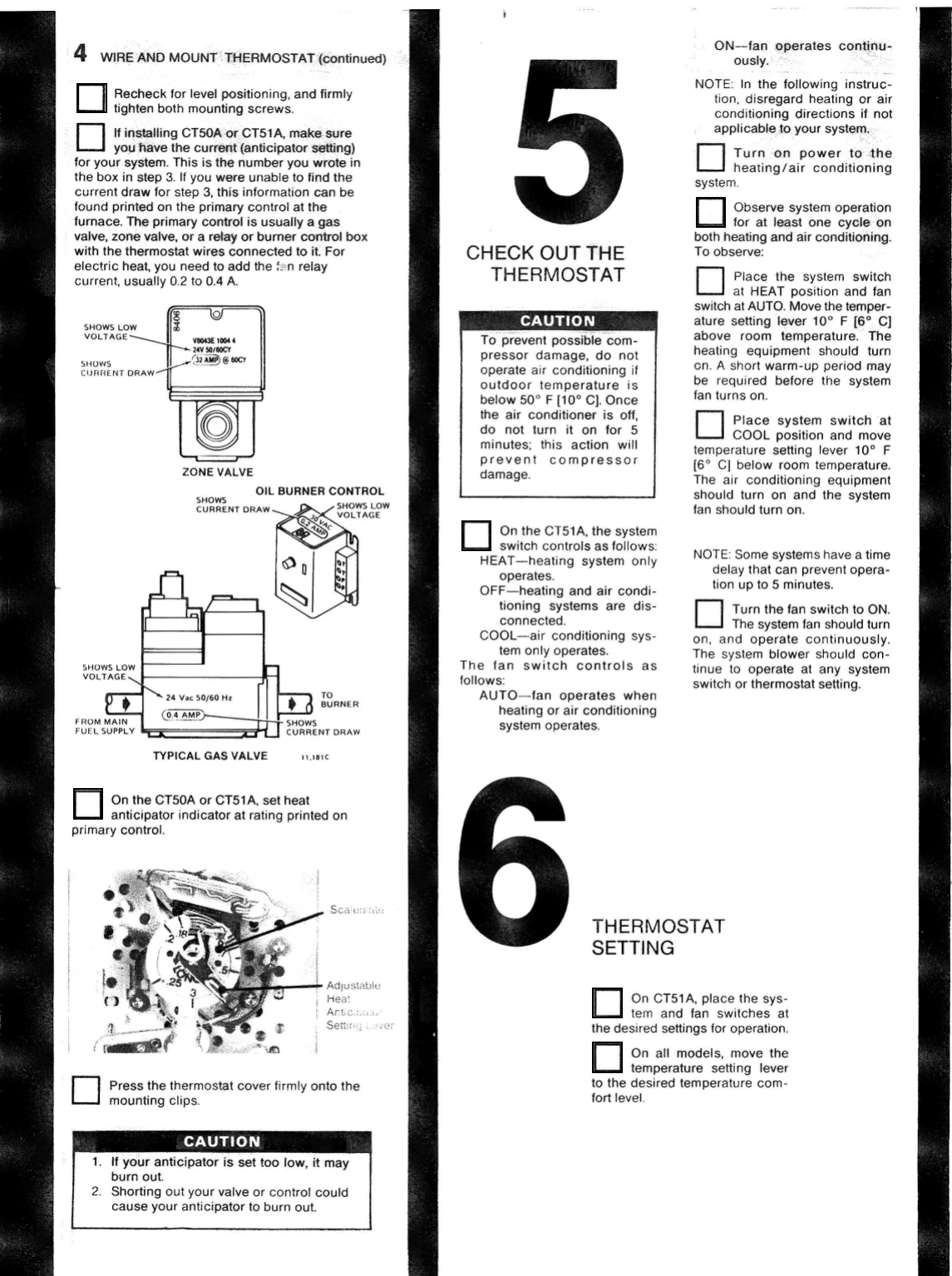
If
installing CTSOAor CT51 A, makssure
CI you Aave the
turf-
{anticipator setting)
for your system. This is the number you wrote
in
the box in step
3
If
you were unable
to
find the
current draw for step
3.
this information can be
found printed on the primary control at the
furnace. The primary control
is
usually
a
gas
valve,
zone
valve, or a retay
or
burner
control
box
with the thermostat wires connected to it. For
electric heat, you need to add the
:.
n relay
current, usually
0
2
to
0.4
A.
ZONE VALVE
OIL
BURNER
CONTROL
SHOWS
CURRENT DRAW
s
LOW
AGE
TO
BURNER
NT
DRAVI
TYPICAL GAS VALVE
ii.iaic
On the CT50A or CT51A, set heat
anticipator indicator at rating printed on
primary control.
Adjuslablt,
Hea'
Ari
c
Set;[.
I
1-
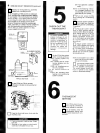
Press the thermostat cover firmly onto the
0
mounting clips
CHECK
OUT
THE
THERMOSTAT
To prevent possible com-
pressor damage, do not
operate air conditioning
if
outdoor temperature is
below
50"
F
[lo0
C]. Once
the air conditioner is
off,
do not turn
it
on
for 5
minutes: this action will
prevent compressor
damage.
On
the CT51A, the system
switch controls as follows
HEAT-heating system only
operates.
OFF-heating and air condi-
tioning systems are dis-
connected
COOL-air conditioning sys-
tem only operates.
The fan switch controls as
follows:
AUTO-fan operates when
heating or air conditioning
system operates
WL
I
ON-fa rates co
ousl
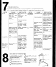
NOTE In the following instruc-
tion, disregard heating or air
applicable
to
your syst
heating/air conditioning
system
Observe system operation
for at feast one cycle
on
both heating and air conditioning.
To observe.
Place the system switch
0
at HEAT position and fan
switch at AUTO. Move the temper-
ature setting laver
10"
F
[So
C]
above room temperature. The
heating equipment should turn
on
A
short warm-up period may
be required before the system
fan turns on.
Place system switch at
0
COOL position and move
temperature setting lever 10"
F
[So
C] below room temperature.
The arr conditioning equipment
should turn on and the system
fan should turn on.
NOTE Some systems have a time
delay that can prevent opera-
tion up to
5
minutes.
Turn the fan switch
to
ON.
0
The system fan should turn
on, and operate continuously.
The system blower should con-
tinue
to
operate at any system
switch or thermostat setting.
{MOSTAT
'ING
On CTSlA, place the sys-
tem and fan switches at
the desired settings for operation.
On all models, move the
temperature setting lever
to the desired temperature com-
fort level