


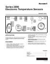
SERIES 2000 ELECTRONIC TEMPERATURE SENSORS
63-2590—05 10
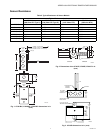
Immersion Well Mounting (C7021D,
C7023D, C7031D, C7041D)
The C7031D Sensor includes an immersion well. The C7021D,
C7023D, and C7041D sensors do not include a well. For the
C7021D, C7023D, and C7041D, order the well as an
accessory (part no.: 50001774-001).
When used on a boiler, follow the manufacturer instructions for
location. If a tapped hole is not provided for the immersion well,
provide one as follows:
1. Drain boiler and drill a 23/32 in. (18 mm) hole at the
selected location.
2. Cut threads in the hole with a 1/2 in. (13 mm) by 14 NPT
tap.
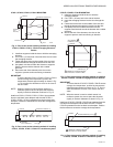
In other installations, mount the immersion well in an elbow
with a heel outlet as shown in Fig. 15.
1. Drain the system, if you have not already done it, and
open the tapped hole.
2. Put pipe joint compound on the threads of the
immersion well and screw it into the tapped hole or
elbow, tightening it securely.
3. Refill the system and check for leaks.
Mount the C7021D, C7023D, C7031D and C7041D into the
well:
NOTE: Mounting using previously installed Honeywell
wells (part no.: 32005960-001) requires an
adapter (part no.: 50001775-001).
1. When an adapter is required, first thread it into the well
no more than one or two turns.
2. Slide the sensor into the well.
3. Rotate the sensor to thread it tightly into the adapter and
the adapter tightly into the well.
Fig. 15. Method of mounting C7021D, C7023D, C7031D,
C7041D Sensor.
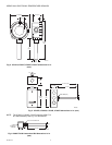
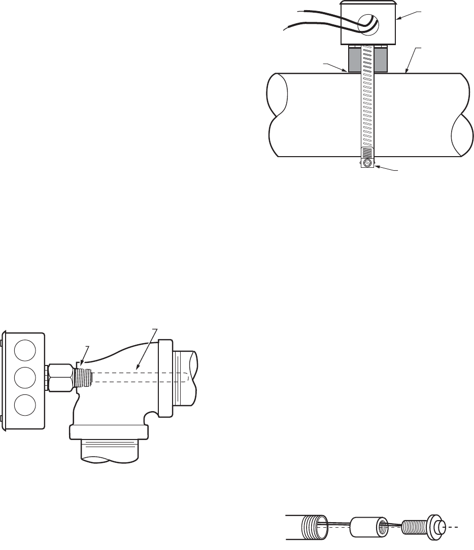
Strap-On Mounting (C7021K, C7023K,
C7041K)
Strap-on mounting is well-suited for retrofit applications where
installation costs can be reduced by not draining the system.
The C7021K, C7023K, C7041K Sensor mounts on metal pipes
from 1-5/8 inch to five inches in diameter using the straps
supplied. Clean the surface of the pipe where the sensor
makes contact before mounting (remove insulation from the
pipe at the point of installation if necessary). Thermal
compound is recommended with the strap-on C7021K,
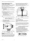
C7023K, C7041K Sensor. Locate the sensor on the discharge
pipe within 3 feet (0.9m) of the boiler. See Fig. 16.
Fig. 16. Strap-on mounting of C7021K, C7023K, C7041K
Sensor.
NOTE: Insulation around the contact area increases sensor
accuracy.
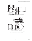
Button Probe Mounting
The C7021P, C7023P, C7041P Button Probe Sensor design
simplifies mounting into a variety of standard structural
materials.
The locking nut can be used to secure the probe. See Fig. 18.
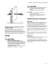
The plastic spacer helps insulate the probe from drywall, wood,
or other material in which the probe is mounted. The spacer is
sized to fit snugly into 1/2 in. metal conduit. See Fig. 17.
NOTES:
— The plastic spacer is threaded for easy installation.
— Use of both the locking nut and spacer requires
cutting spacer to shorter length.
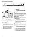
C7041P MOUNTING RECOMMENDATIONS
Determine the proper location based upon the following:
— Mount the probe to an inside wall approximately 54 in.
(1372 mm) from the floor (or in the specified location) to
allow exposure to the average zone temperature.
— Do not mount the probe to an outside wall, a wall containing
waterpipes, or near air ducts.
— Avoid locations exposed to register discharge air, or
radiation from lights, appliances, or the sun.
Fig. 17. Mounting sensor in conduit.
1/2 NPT (13)
M22135
SENSING ELEMENT
(SEALED IN STAINLESS STEEL
TUBE INSIDE OF INSERTION WELL)
M22136
SENSOR
PIPE
COPPER PLATE MUST
MAKE GOOD CONTACT
WITH METAL PIPE
WORM GEAR
M22797