


SERIES 2000 ELECTRONIC TEMPERATURE SENSORS
63-2590—05 8
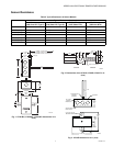
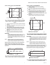
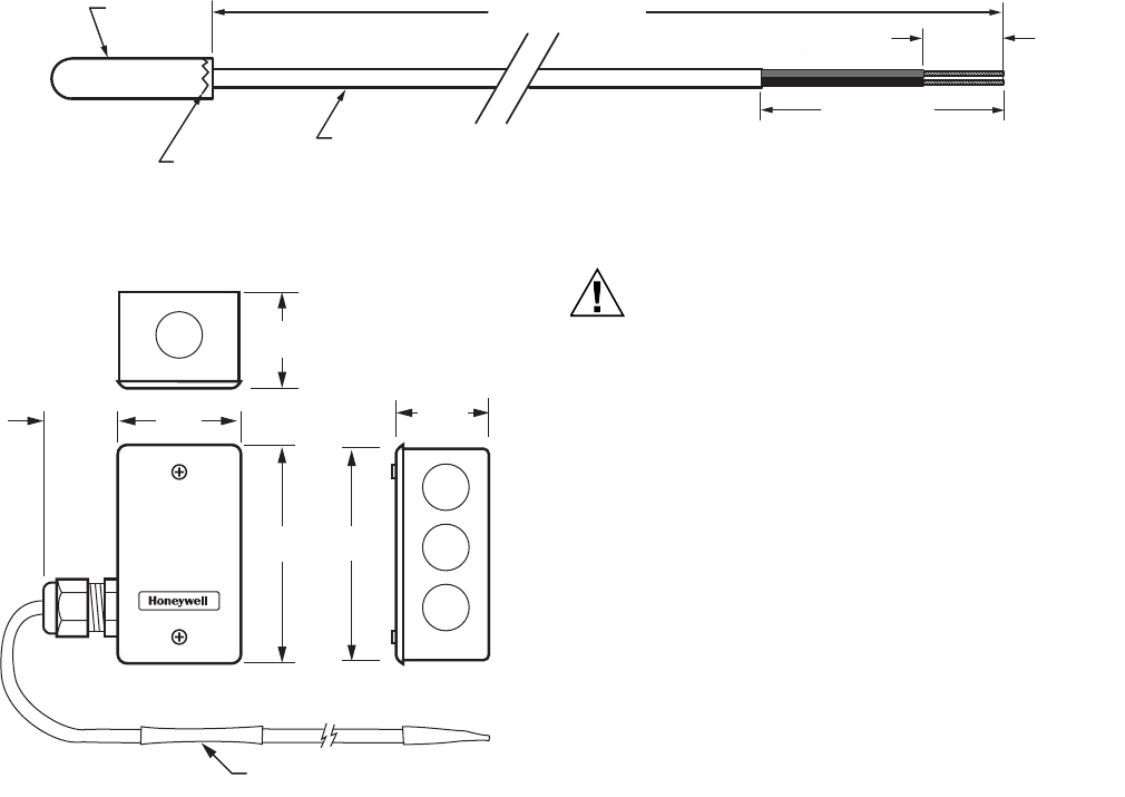
Fig. 9. C7021N, C7023N, C7041N dimensions in in. (mm).
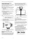
Fig. 10. C7021J, C7023J, C7031J, C7041J dimensions in in.
(mm).
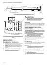
INSTALLATION
When Installing this Product...
1. Read these instructions carefully. Failure to follow them
could damage the product or cause a hazardous
condition.
2. Check the ratings given in the instructions and on the
product to make sure the product is suitable for your
application.
3. Installer must be a trained, experienced service
technician.
4. After installation is complete, check out product
operation as provided in these instructions.
CAUTION
Electrical Shock or Equipment Damage Hazard.
Can shock individuals or short equipment
circuitry.
Disconnect power supply before installation.
Mounting
The method of mounting depends on the particular application
of the temperature sensor. The following procedures include
outdoor, duct, immersion well and strap-on applications. Also
refer to the instructions for the electronic control.
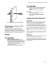
Outdoor Mounting (C7031G, C7021F,
C7023F, C7041F)
The C7031G, C7021F, C7023F and C7041F sense outdoor air
temperature. Mount this control where it can sense average
outdoor air temperature. Normally, the north side of a building
provides a suitable location.
NOTE: These sensors are weatherproof for outdoor use.
Knockouts allow for 1/2 in. conduit connection.
1. Remove and set aside the wiring box cover.
2. Mount the sensor to standard 1/2 in. conduit.
NOTE: Mount sensor so that the element points down.
3. Make wiring connections using two wire nuts.
4. Reattach the wiring box cover.
Duct Mounting
The C7031B, C7031J, C7021B/C/J, C7023B/C/J, C7041B/C/J
can be mounted in a duct to sense air temperature.
IMPORTANT
Select a spot for the sensor where it will be exposed
to average duct air temperature. Avoid locations
where stratification can cause sensing errors.
C7021B,C/C7023B/C, C7041B/C MOUNTING
1. Cut a hole in the duct just large enough to accept the
sensing element.
2. Use the sensor case to mark the locations of the pilot
holes for the mounting screws.
3. Drill the pilot holes and fasten the sensor to the duct.
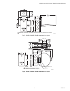
POTTING MATERIAL LEVEL
0.063 MAX. FROM TOP OF PROBE
CONDUCTOR CABLE
6 FT ± 6 IN (1829 ±152)
PROBE
1 X Ø 1/32 (1)
2 ± 1/2 (51 ± 13)
STRIP LENGTH
2X 1/4 (6)
M33019
2-5/16
(59)
1(25)
1-11/16
(43)
4-3/16
(107)
4 THERMISTORS PLACED
ON A 12 FOOT (3.7M) WIRE.
4
(70)
1-11/16
(43)
M22133