


60-0164—1
3
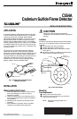
C554A CADMIUM SULFIDE FLAME DETECTOR
OIL LINE
SCREW
OIL LINE ADAPTER
BRACKET
TO
NOZZLE
MOUNTING
BRACKET
LEADWIRE
SOCKET
PLUG-IN
CELL
M7856
Fig. 5. Use oil line adapter bracket to mount
C554A on oil line.
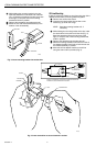
Wiring
Disconnect power supply before beginning wiring to
prevent electrical shock or equipment damage.
All wiring must comply with local electrical codes and
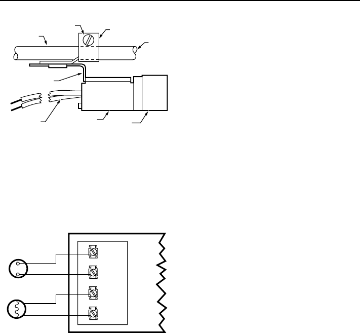
ordinances. See Fig. 6 for a typical C554A hookup to the
oil burner primary control.
T
T
F
F
THERMOSTAT
(24 VOLT)
C554A
CAD CELL
OIL BURNER RELAY
M7858
Fig. 6. Typical hookup for C554A to oil
burner primary control.
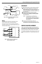
CHECKOUT
To check cad cell operation, use the following procedure:
³ Disconnect cad cell leadwires; then start burner.
Shortly after burner starts, place a temporary jumper
between terminals F-F. Connect an ohmmeter
across cad cell leadwires; resistance should be less
than 1600 ohms.
· Stop burner and remove temporary jumper.
» With burner off, check dark cell resistance across
cad cell leadwires. Resistance should be greater
than 20,000 ohms.
NOTE: If cell resistances are different than
specified, recheck wiring and location of
cell. If necessary, replace plug-in portion of
cell, Honeywell part no. 130367 Replace-
ment Cad Cell.
¿ Reconnect cad cell leadwires. Check the
Protectorelay (burner sequencing relay) control
according to the instructions packed with the control.
SERVICE AND REPLACEMENT
Under normal operating conditions, the C554A does not
require cleaning. If a badly adjusted burner causes heavy
accumulation of dirt and soot on the cell surface, carefully
wipe the cell surface to restore full view of the oil flame.
If the C554A is damaged, replace the plug-in portion of the
cell. Order Honeywell part no. 130367 Replacement Cad
Cell.