


3
ANN-RLY Module Document # 53033 Rev. B 10/10/07 ECN 07-744
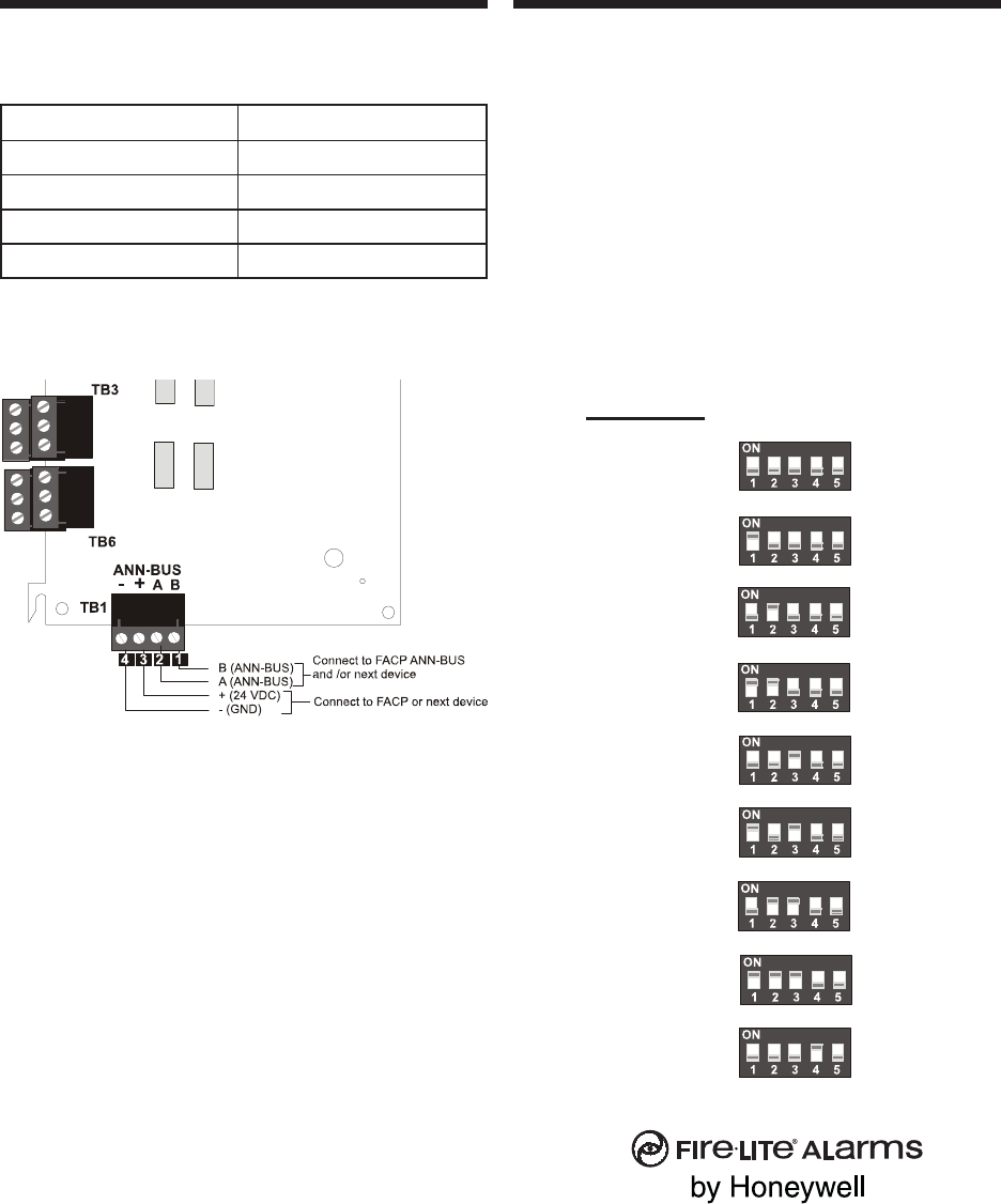
Wiring ANN-RLY Module to FACP
Refer to Table 2 and Figure 3 for wiring
connections.
)1BT(slanimreTYLR-NNAslanimreTSUB-NNAPCAF
)-(4lanimreT)-(
)+(3lanimreT)+(
)A(2lanimreT)SUB-NNA(A
)B(1lanimreT)
SUB-NNA(B
Table 2: Wiring ANN-RLY Module to FACP
ANN-RLY Relay Module
Figure 3: Wiring ANN-RLY Module to an FACP
Notes:
1. All connections/sources are to be power-limited
and supervised.
2. 12 - 18 AWG (0.75 - 3.25 mm
2
) wire for 24
VDC circuit is acceptable. Refer to the
appropriate FACP manual.
3. Power wire distance limitation is set by 1.2 volt
maximum line drop from source to end of
circuit.
4. Maximum distance from FACP to last ANN-
BUS device must not exceed 1,250 feet
(380 m). Refer to Wiring Distance Table in
appropriate FACP manual for wire gauge and
distance limitations.
5. Common, Normally Closed and Normally Open
terminals for each relay follow the same
pattern as illustrated above.
Setting DIP Switches
Each ANN-BUS device requires a unique address.
ANN-RLY relay module DIP switch SW1 is used
to set the address for the annunciator.
A maximum of 8 devices can be connected to the
FACP ANN-BUS communication circuit. ANN-
BUS device addresses do not need to be sequential
and can be set to any number between 01 and 08.
Note that 00 is not a valid address. The following
illustrates the DIP switch settings for each address
(ID Number):
One Fire-Lite Place
Northford, CT 06472
USA TEL: (203) 484-7161
www.firelite.com
© 2006 Fire-Lite Alarms P/N: 53033
ID Number
(Address)
(not valid) 00
01
02
03
04
05
06
07
08
DIP Switch SW1
C
NC
NO
C
NC
NO