


HONEYWELL MODEL 700/800 SIGNAL PROCESSOR AND VIEWING HEAD
66-2069—02 12
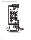
INCREASE, DECREASE and STORE buttons (range
of 00 to 29).
• LOAD FACTORY DEFAULTS button:
— Used to restore all settings to the factory default
values
•
↑ INCREASE button:
— Used to increase parameter value when in
programming mode
• RATIO (%) RELAY OFF/RELAY ON button:
— Used along with the INCREASE, DECREASE and
STORE buttons to set the RELAY OFF setpoint at a
percentage of the RELAY ON setpoint. Adjustable
from 20% to 80%.
•STORE button:
— Stores new parameter values during programming
— After making changes “--” will be displayed indicating
the new values are accepted and stored
•
↓ DECREASE button:
— Used to decrease parameter value when in
programming mode
• BNR-ON SEQ START/END button:
— Used to initiate and proceed through the automatic
parameter setup sequence, which includes the RELAY
ON, RATIO (%) and GAIN settings (the FFRT, mA
output and communication address must be set
manually)
• BNR-OFF SEQ START/END button:
— Used during the automatic parameter setup sequence
• ACCEPT RATIO/SET GAIN button:
— Allows user to set the viewing head gain in conjunction
with the INCREASE, DECREASE and STORE buttons
— Used in conjunction with the BNR-ON SEQ START/
END and BNR-OFF SEQ START/END buttons during
the automatic setup process
• FFRT 1/2/3 SEC OPTION button:
— Used to set the FFRT timing along with the
INCREASE, DECREASE and STORE buttons
• 0-20MA 4-20MA OPTION button:
— Used in conjunction with the INCREASE, DECREASE
and STORE buttons to select the proportional mA
output for the flame signal
• RESET rE button:
— Resets a lockout condition
— Also used to exit a menu while programming
— Used to set the Modbus address along with the
INCREASE, DECREASE and STORE buttons
Manual Setup of Setpoints
The keypad of the signal processor is used to set the IR/UV
GAIN, RELAY ON, RATIO % (Relay Off), FFRT and mA output
option setpoints. The following section describes this process.
Also refer to Fig. 22, 23, 24, 25 and 26.
Setting the Viewing Head Gain
The gain of the IR and UV viewing heads can be adjusted. In
addition to the information in this section, refer to Fig. 26. At
power-up, the 700 signal processors display codes to tell the
operator what type of viewing head and what gain is being
used. Default values are “r5” for the IR viewing head and “u5”
for the UV viewing head. The “r” or “u” denote IR or UV
viewing heads, respectively, while the numeric digit indicates
the current gain setting. The gain can be adjusted from 1 to 9
with a gain of 5 being the factory default gain.
To change the gain, press and hold the SET GAIN button for
two seconds until the current value is displayed. Use the
INCREASE and DECREASE buttons to change the setting as
appropriate while the value is displayed. To store the new
setting, press the STORE button until “- -” is shown, indicating
the value has been accepted.
If no activity occurs for a period of four seconds while the
value is displayed, the display will return to the operation
mode without saving the new setpoint.
To exit the menu at any time without saving changes, simply
press the RESET/rE button.
The gain is live; changes are effective immediately, but if the
displayed gain value is not stored (by pressing STORE), and
no other buttons are pressed, the processor returns to the
previous setting after four seconds.
Relay On Setpoint
The two numeric digits on the Model 700 signal processor
normally display the incoming count during operation; that is,
the number of pulses that arrive between self-check pulses.
This count ranges from 00 to 29.
Refer to Fig. 22 for a flowchart of setting the Relay On
setpoint. Press and hold the RELAY ON SETPOINT key for
two seconds to access this setpoint. The RELAY ON SET
POINT value will be displayed. If no further keys are pressed,
this display will disappear in four seconds and the incoming
count will again be displayed. If the RESET key is pressed,
the display will return immediately to displaying the incoming
count.
While the RELAY ON SET POINT is displayed, you may
increase or decrease the setting by using the INCREASE and
DECREASE arrow keys. To store the new setting, press the
STORE button until “- -” is shown, indicating the value has
been accepted.
To exit the menu at any time without saving changes, simply
press the RESET/rE button or wait 4 seconds until the display
reverts to the incoming count value. To extend the display
time, press the RELAY ON SETPOINT button again; the
display will time out for four seconds after the key is released if
no other buttons are pressed.
The displayed value of the RELAY ON SET POINT is live; that
is, if the relay is off and the adjusted value falls below the
current flame signal count, the relay will turn on immediately
(FFRT settings are ignored). This immediate response can be
seen if the count is low and the RELAY ON SET POINT is set
above it; if the RELAY ON SET POINT is then adjusted down
to the count level, the FLAME ON relay will be energized.
Ratio (%) Relay Off/Relay On Setpoint
For a flowchart of this setpoint process, refer to Fig. 23. The
key labeled RATIO (%) RELAY OFF/RELAY ON is used to set
the RELAY OFF SET POINT at a percentage of the RELAY
ON SET POINT. This percentage is adjustable from 20% to
80%. For example, if the RELAY ON SET POINT is set to 16
and the RATIO (%) is set to 50% (the factory default values)
the relay will energize if the displayed count goes to 16 or
higher and de-energize when the count drops to 08 or less for
one to three seconds, depending on the FFRT (Flame Failure
Response Time) setting. The adjustment of the RATIO setting