


WIRELESS COMMUNICATION CARD FOR TB7200/7300/7600 SERIES COMMUNICATING THERMOSTATS
62-2020—03 2
INSTALLATION
CAUTION
Erratic System Operation Hazard.
Failure to follow proper wiring practices can introduce disruptive electrical interference (noise). Keep wiring at
least one foot away from large inductive loads such as motors line starters, lighting ballasts, and large power
distribution panels.
Shielded cable is required in installations where these guidelines cannot be met.
Ground shield only to grounded controller case.
IMPORTANT
All wiring must comply with local electrical codes and ordinances or as specified on installation wiring dia-
grams.
• Power to the WEBs-AX controller must be OFF when installing or removing the wireless communication card or
damage will occur! Also, be careful to plug the wireless communication card into its connector properly (pins
aligned).
• Only one the wireless communication card can be installed in a WEBs-AX controller. Always install the card in option
slot 1 in WEB-2xx and WEB-6xx models. Option slot 1 or 2 can be used on WEB-7xx models.
Mounting the wireless communication card on a WEBs-AX controller
1. Remove power from the controller.
2. Remove the controller cover. To do this, press in the four tabs on both ends of the unit, and lift the cover off.
NOTE: If other expansion accessory modules are
plugged into the controller, you may need to
slide them away from the unit to get to the cover
tabs.
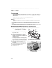
3. Remove the battery and bracket assembly by taking out
the four screws. (Fig. 1)
4. Unplug the battery from the connector on the controller.
5. Remove screws and battery assembly.
6. Remove the front blanking end plate for option slot 1
(Com1) on WEB-2xx and WEB-6xx controllers and
option slot 1 or 2 (Com3 or Com4 in the WEBStation-AX)
on WEB-7xx controllers.
7. Carefully insert the pins of the wireless communication
card into the appropriate socket. The mounting holes on
the option board should line up with the standoffs on the
base board. If they do not, the connector is not properly
aligned. Press until the option card is completely seated.
8. Plug the battery cable back into the battery connector on
the controller
9. Set the battery and bracket assembly back over the
option card slots, with the mounting holes aligned with
the standoffs.
10. Re-fasten screws through battery bracket the four hold-
ing screws through. DO NOT over tighten.
11. Replace the controller cover.
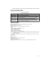
12. Install the antenna. (Fig. 2)
M32538
SCREWS (4)
UNPLUG
BATTERY HERE
OPTION
SLOT 2
AREA
WEB/
CP-201/
600/
700
OPTION
SLOT 1
AREA
BLANKING
END PLATE
BATTERY
ASSEMBLY
(INCLUDES
CABLE AND
BRACKET)
Fig. 1. Removing battery and bracket assembly
Fig. 2. Antenna location