


PIR APPLICATION GUIDE FOR TB7200 AND TB7300 SERIES THERMOSTATS
33 63-4526—01
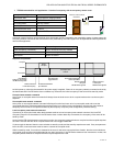
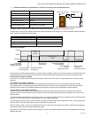
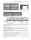
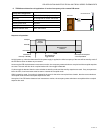
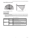
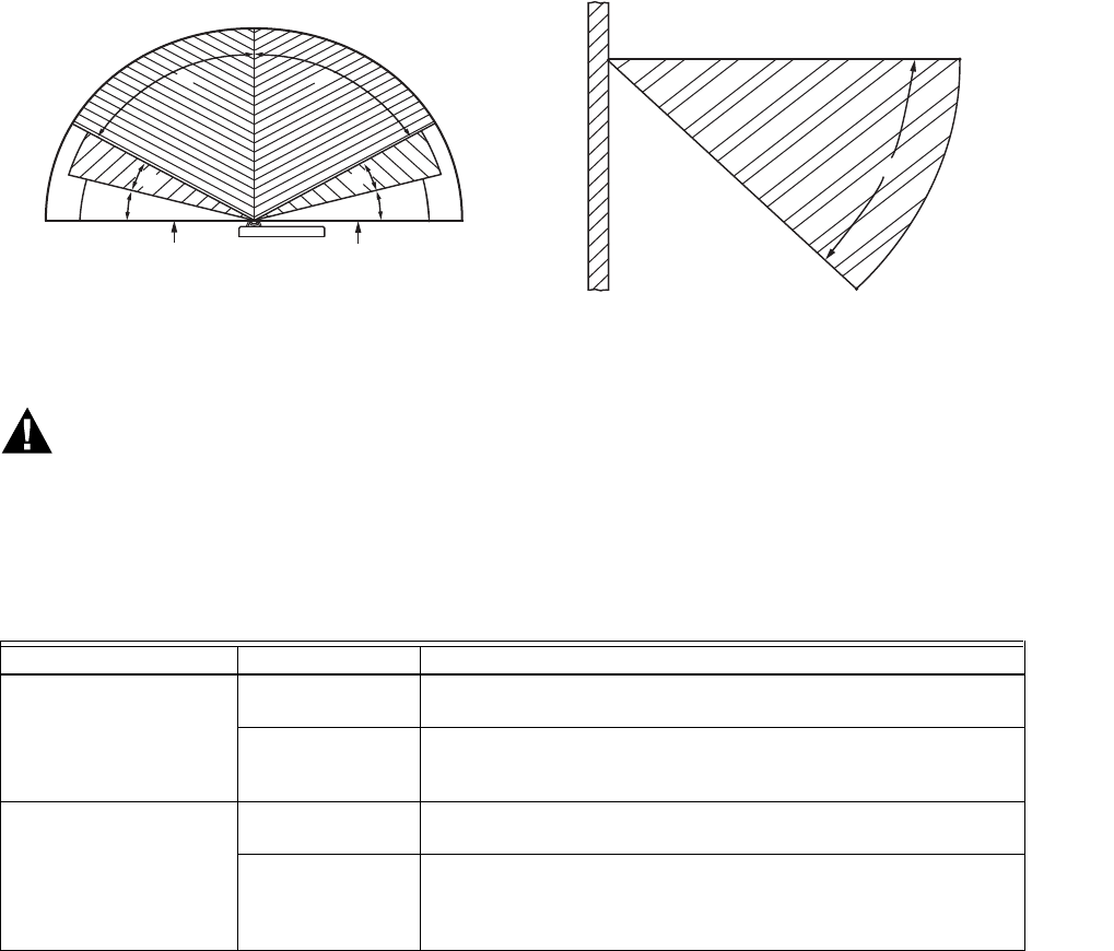
Typical PIR Detection Pattern
INSTALLATION
WARNING
Electronic controls are static sensitive devices. Discharge yourself properly before manipulation and installing
the thermostat and its accessories.
Short circuit or wrong wiring may permanently damage the thermostat or the equipment. All TB7200 and 7300 Series
thermostats are to be used only as operating controls. Whenever a control failure could lead to personal injury and/or loss
of property, it becomes the responsibility of the user to add safety devices and/or alarm system to protect against such
catastrophic failures.
Table 2. Installation Tips
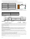
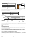
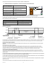
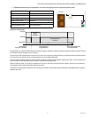
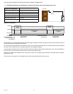
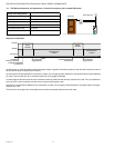
Fig. 3. Typical Horizontal Angle Fig. 4. Typical Vertical Angle
Tip Type Area Of Interest Explanation
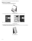
General Installation PIR Connector Polarized connector is located at bottom left hand corner of TB7200
or TB7300 Series thermostat
Security Screw A security screw has been provided in the thermostat box. This
screw should be carefully installed in the intended mounting position
located bottom center of thermostat cover.
Initial Power Up &
Commissioning
PIR Warm up
period
PIR Sensor may take up-to 60 seconds after initial warm up period to
detect movement consistent with typical detection pattern.
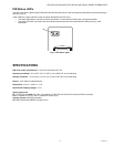
Visual indication
(Status of PIR)
Visual indication of PIR activity for commissioning is provided via a
blinking LEDs located on the thermostat cover under the PIR lens.
LEDs will be active while occupant is in field of detection pattern for a
period of 30 minutes after initial power up.
15°
15° 15°
15°
60° 60°
ZONE NOT RELIABLE ZONE NOT RELIABLE
0°
M21308
45°
20 FEET
CENTER
M21309