


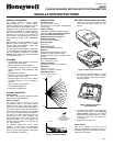

Page 3
TEST PROCEDURES
Important:
Testing should be conducted with
the protected area cleared of all people. Place
the protective system's control in the Test
mode for the Walk Test procedure. When the
PIR senses movement, the system's console
emits a beep, verifying that the PIR's
transmitter signal has reached the control's
wireless receiver.
The absolute range of all PIR units is subject to
variation because of different types of clothing,
backgrounds, and ambient temperature. For
this reason, ensure that the most likely intruder
routes are well within the PIR's protective
zones and that Walk Testing is carried out
along these routes.
WALK TEST
Test mode is initiated by removing and
replacing the detector’s front cover, or by
removing and replacing the sensor from the
mounting plate.
Note: Each time you remove and replace the
front cover, or remove and replace the sensor
in the mounting plate, the sensor will transmit
every alarm signal for 64 alarm events.
1. Remove front cover, and set the pulse
count jumper as required in the installation
(INT, STD or HARSH),
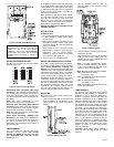
2. Enable the LED by placing the jumper link
in the TEST position (see Figure 4 for
jumper location).
Note: Removing the front cover, or
removing the sensor from the mounting
plate, will also enable the LED.
3. Replace front cover and walk through
protective zones, observing that the
detector's LED lights whenever motion is
detected (the LED serves as a Walk Test
indicator during this procedure).
4. After the Walk Test is completed, disable
the LED by placing the LED jumper link
in the Normal position. Failing to do so
will reduce the battery life. (see Figure 4.)
MAINTAINING PROPER OPERATION
In order to maintain the detector in proper
working condition, it is important that the user
observes the following:
1. Replace all three batteries within seven (7)
days after a "low battery" message has
appeared in the system's display.
2. Detectors should never be re-aimed or
relocated without the advice or assistance
of the alarm service company.
3. The physical surroundings of the protected
area should not be changed. If furniture or
stock is moved, or air conditioning or
additional heating is installed, the PIR may
have to be readjusted.
4. Walk Tests should be conducted frequently
(at least weekly) to confirm continued
proper coverage.
SPECIAL INSTRUCTIONS FOR INSTALLATION WITH PETS
To take full advantage of the pet immunity in the 5894PI, the guidelines below should be followed:
• Mount the center of the detector 7.0 feet high.
• Set the Pulse Count to Standard or Harsh.
• Mount where animals/rodents cannot come within six feet of the detector by climbing on
furniture, boxes, or other objects.
• Do not aim the detector at stairways or furniture / objects that can be climbed by an animal.
Note:
This unit will provide immunity to false alarms for an individual animal or a group of animals
whose total weight is equal to or less than 80 pounds when the room temperature is above 50° F.
TROUBLESHOOTING
Trouble 1: INTERMITTENT ALARM
Probable Causes:
A. Rapid temperature change. Check for electric or gas heaters,
open flames, electric arcs, etc.
Remedy:
Locate source and re-position detector.
B. Drafts causing drapes, light fixtures, display material to move.
Remedy:
Eliminate source of motion.
Trouble 2: LED INOPERATIVE DURING WALK TEST
Probable Causes:
A. LED control jumper set to NORMAL position.
Remedy:
Re-position jumper to TEST position (see Figure 4).
B. LED malfunction. Check for broken/shorted leads.
Remedy:
Return unit for service.
Trouble 3: LED OPERATIVE WITH LED JUMPER LINK SET
TO NORMAL (OFF) POSITION
Probable Causes:
A. The sensor is not mounted squarely on the wall, (the wall
tamper switch is not depressed.)
Remedy:
Re-position the sensor to make sure the wall
tamper switch is fully depressed.
B. The sensor’s front cover is not installed.
Remedy:
Replace the sensor’s front cover.
Trouble 4: SUPERVISION FAILURE
Probable Causes:
A. When enrolling the detector, a tamper signal was used to transmit
the detector serial number, and the panel enrolled the detector with a
loop type “4”, or the wrong device was learned.
Remedy:
Ensure the serial number and loop types are correct for
each detector; if the detector loop type is programmed as “4”,
manually change it to “1” at the panel. If the wrong device was
learned, enroll the detector again (see Programming on page 2).
B. The detector was placed in a location where the RF signal is not
strong enough.
Remedy:
Repeat the directions to verify the transmission path (see
the Radio Transmission Path Check section on page 2). If
necessary, move the detector to a new location.
Trouble 5: UNIT DOES NOT APPEAR TO BE OPERATING
Probable Cause:
A. Unit is not receiving power.
Remedy:
Check for appropriate battery voltage. Install new batteries
if necessary. Be sure to change all batteries.
Trouble 6: UNIT IS ALWAYS IN TEST MODE
Probable Cause:
A. The sensor front cover was removed and replaced, or the sensor
was removed and replace in the mounting plate, so the sensor is
transmitting every alarm signal for 64 alarm events.
Remedy:
Wait for the sensor to transmit 64 alarm events.