


Installation
10/07 Installation and Maintenance Manual 7
3.5 Torque Recommendations
For inserting a cell in metal fittings or bushings - 40 ft-lb maximum. For inserting a cell in plastic fittings
or bushings - 10 ft-lb maximum. Always use pipe sealant (preferably Teflon tape).
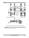
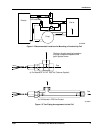
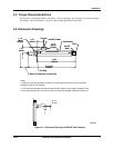
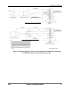
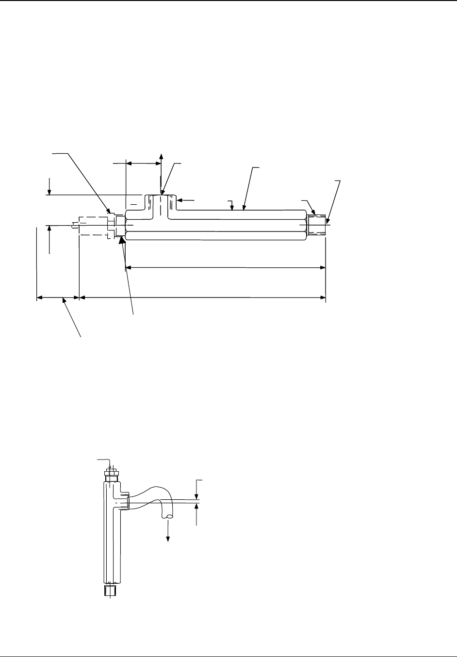
3.6 Dimension Drawings
CELL
IN
11/2"
(38mm)
83/4"
(222mm)
14 1/2" max
(368mm)
3/4" Fitting
Allow 4 1/8" (105mm) for re
CELL
IN
11/2"
(38mm)
83/4"
(222mm)
14 1/2" max
(368mm)
3/4" Fitting
Allow 4 1/8" (105mm) for re
moval of cellmoval of cell
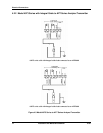
3/4" NPT
(Male)
Flow In
Flow Chamber
11/2"
(38mm)
Octagon
3/4" NPT (Female)
Flow Out
11/2"
(38mm)
11/8"
(38mm)
Hexagon
3/4" NPT
(Male)
Flow In
Flow Chamber
11/2"
(38mm)
Octagon
3/4" NPT (Female)
Flow Out
11/2"
(38mm)
11/8"
(38mm)
Hexagon
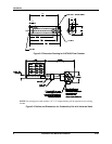
2" min.
(51mm)
CELL I N
a/n 23342
Notes:
1. Mount cell and flow chamber horizontally as shown above with flow exit up to eliminate
possible air gap around cell body.
2. If cell and flow chamber must be mounted vertically, attach a short length of tubing to flow
exit as shown below and form a trap to ensure filling of flow chamber, especially at low flow.
Figure 3-1 Dimension Drawing for 055919 Flow Chamber