


Audio Command Center Series Manual — P/N 51889:E1 6/8/2010 103
Appendix B: Addressable Module Connections
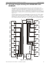
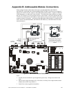
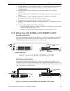
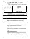
When configured with an addressable FACP such as the MS-9200UDLS, MS-9200UD,
MS-9200C(E), or MS-9600, the AUDIO•COMMAND•CENTER•25/50 Series may be triggered
either by the FACP main NAC output or from addressable control modules. Figure B.1 illustrates
CMD1 triggered by an addressable control module. The addressable control module may trigger
the ACC-25/50 Series via reverse polarity (shown) or relay contact. The FACP monitors the ACC-
25/50 Series for faults while in the standby or alarm state by wiring a monitor module to the trouble
contacts as shown in Figure B.1. Activation of the addressable control module is controlled by the
FACP. Refer to the MS-9200UDLS, MS-9200UD, MS-9200C(E), or MS-9600 manual for addi-
tional information.
Notes:
1. Auxiliary Power terminals for special application power only. Wiring must remain in the
room.
2. Supervise the wiring between the ACC-25/50 Series Auxiliary Power output and the control
module with an EOL relay (EOLR-1).
3. End-of-Line resistor supplied with modules.
+
+
+
-
-
-
EXT.AUDIO
INPUT
SECONDARY AMP
PRIMARY AMP
EXT.AUDIO
INPUT
LOCAL
PLAYBACK
ZONE PAGE MODULE
ZONE PAGE MODULE
MICROPHONE
TROUBLE
RELAY
REMOTE
MIC INPUT
EXT PAGE
INPUT
AUX
POWER
MASTER
CMD OUT
CMD5 IN
CMD4 IN
CMD3 INCMD1 CMD2
S5
S1
S3
JP1
AC PWR
BATT TBL
CHG TBL
GND FLT
P5
P13
S2
RECORD
BYPASS
P3
P4
P2
P1
P9
P6
1 2 3 4 5 6 7 8
ON
1 2 3 4 5 6 7 8
ON
1 2 3 4 5 6 7 8
ON
TB7
TB6 TB4
TB2
TB5
TB8
TB9
TB1
TB10
P10
P11
- +
BATTERY
CHGR DISABLE
AC HOT NEUT EARTH
P1
TB3
CB1
P12
Figure B.1 Addressable Module Connections
Monitor
Module*
Control
Module*
a
c
c
2
5
m
d
s
t
p
h
.
w
m
f
SLC
SLC
Output
24 VDC
T11
T10
T9
T8
T7
T6
T1
T2
T3
T4
T5
T11
T10
T9
T8
T7
T6
T1
T2
T3
T4
T5
Output
EOL Power Supervision
Relay (EOLR-1)
Note 2
4.7K ELRs PN: 27072
Note
3
Note
3
4.7K ELR
PN: 27072
Specific
Application
Power
Note 1
ZONE 1
MESSAGE 1
POWER ON
SYSTEM
TROUBLE
MESSAGE
TROUBLE
GENERATOR
TONE
GENERATOR
TROUBLE
RECORD
PLAYBACK
TROUBLE
SILENCE
MICROPHONE
TROUBLE
*If the SLC device does not match the
one in this figure, refer to the SLC
manual devices wiring conversion
charts for the legacy and newer type
modules.