


2
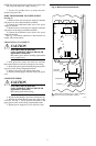
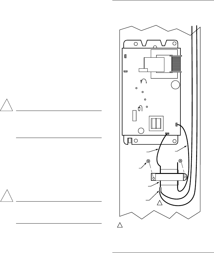
NOTE: Be sure the transformer terminals are located on the
side away from the power supply. See Fig. 2.
7. Use the two provided screws to secure the trans-
former to the power box.
WIRE TRANSFORMER TO POWER SUPPLY
(See Fig. 2)
1. Remove black wire from power supply P1 terminal
and place it on one of the transformer terminals.
2. Connect the transformer black lead to the power
supply P1 terminal.
3. Remove brown wire from power supply P2 terminal
and place it on the empty transformer terminal.
4. Connect the transformer brown lead to the power
supply P2 terminal.
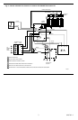
See Fig. 3 for internal schematic for the electronic air
cleaner with conversion kit.
CHANGE PLUG TO CONDUIT
CAUTION
ELECTRIC SHOCK HAZARD.
CAN CAUSE ELECTRICAL SHOCK OR
EQUIPMENT DAMAGE.
Disconnect power before installing replacement
power supply board.
1. In the power box, remove and retain two wire nuts
that connect the line cord leads to the power box wiring.
2. Remove the power green lead from the green ground-
ing screw on the wiring compartment barrier.
3. Remove the power cord and the strain relief.
4. Put the provided plug in the hole left by the power
cord.
COMPLETE WIRING
CAUTION
ELECTRIC SHOCK HAZARD.
CAN CAUSE ELECTRICAL SHOCK OR
EQUIPMENT DAMAGE.
Disconnect power before wiring.
1. Attach conduit through a power box side knock-out.
2. Wire the air cleaner directly to the line voltage using
wire nuts. See Fig. 3. Secure ground connection to the
green ground screw on the wiring compartment barrier.
3. Replace power supply box, cover and access door.
Fig. 2—Mount and wire transformer.
!
!
P3
P4
P1
P2
M5767
2
4
3
1
J2
R43
MOUNTING
SCREWS (2)
BLACK
LEAD
TERMINALS
TRANSFORMER
BROWN
LEAD
BROWN
BLACK
1
1 BROWN AND BLACK WIRES OFF OF P1 AND P2 TERMINALS
CAN GO ON EITHER TRANSFORMER TERMINAL.